
S60 L5-2.4L VIN 64 B5244S6 (2003)
(CMP) sensor, a signal is transmitted to the engine control module (ECM) from the camshaft position (CMP) sensor. A low signal is transmitted to the
engine control module (ECM) when the camshaft position (CMP) sensor is between two teeth.
The camshaft position (CMP) sensor is positioned at the rear of the engine on the camshaft with continuous variable valve timing (CVVT). On vehicles
with twin camshaft position sensors, the signals are offset in relation to each other. This allows the cylinder to be identified more quickly.
The engine control module (ECM) can diagnose the camshaft position (CMP) sensor.
Knock sensor (KS)
The function of the knock sensor (KS) is to monitor combustion knocking from the engine. Knocking may damage the engine and reduces the efficiency
of engine combustion.
If the engine control module (ECM) registers knocking from any of the cylinders, the ignition will be retarded for that cylinder at the next combustion
stage. If repeated ignition retardation does not prevent knocking, the injection period will be increased. This has a cooling effect.
The sensor is made up of a Piezo electrical crystal. If there is engine knock, vibrations (sound waves) spread through the cylinder block to the knock
sensor (KS). The resultant mechanical stress in the Piezo electrical material in the knock sensors generates a voltage. This signal is transmitted to the
engine control module (ECM). The signal corresponds to the frequency and amplitude of the sound waves. This allows the Engine Control Module
(ECM) to determine if the engine is knocking. The camshaft position (CMP) sensor and engine speed (RPM) sensor are used to determine the operating
cycle of the engine (which cylinder is igniting) and thereby which cylinder is knocking.
The knock sensor (KS) is positioned on the cylinder block below the intake manifold.
The engine control module (ECM) can diagnose the knock sensor (KS).
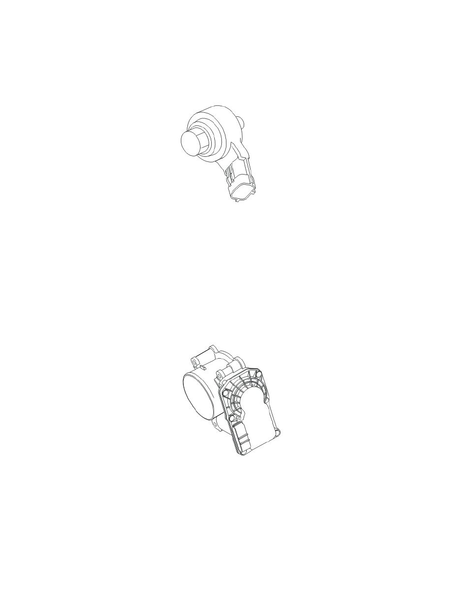
Electronic throttle unit
The electronic throttle unit, using the PWM control signal from the engine control module (ECM), regulates the amount of air for engine combustion.
This is done using an electronically controlled shutter.
The aluminum electronic throttle unit consists of a round throttle disc on a spindle. The spindle is driven by a DC motor (damper motor), gear wheel and
two springs; one for opening and one for return.
By changing the polarity of the power supply, the DC motor can be run in both directions. At one of the limit positions the throttle disc is closed so that
minimal air can pass the throttle unit. In the other limit position, the throttle disc is parallel to the air flow. This provides maximum airflow through the
electronic throttle unit.
Two permanent magnets in the gear sector on the throttle spindle are used to check the position of the throttle disc. The permanent magnets affect two
throttle position (TP) Hall sensors in the cover. The analog signals from the two sensors are transmitted to the engine control module (ECM). The signals
are offset. The engine control module (ECM) compares these signals with the stored desired values to check if they are plausible.
The electronic throttle unit is located on the engine intake manifold. In the event of a fault, the throttle unit must be replaced as a single unit.
The engine control module (ECM) can diagnose the electronic throttle unit.