
S60 L5-2.4L VIN 64 B5244S6 (2003)
-
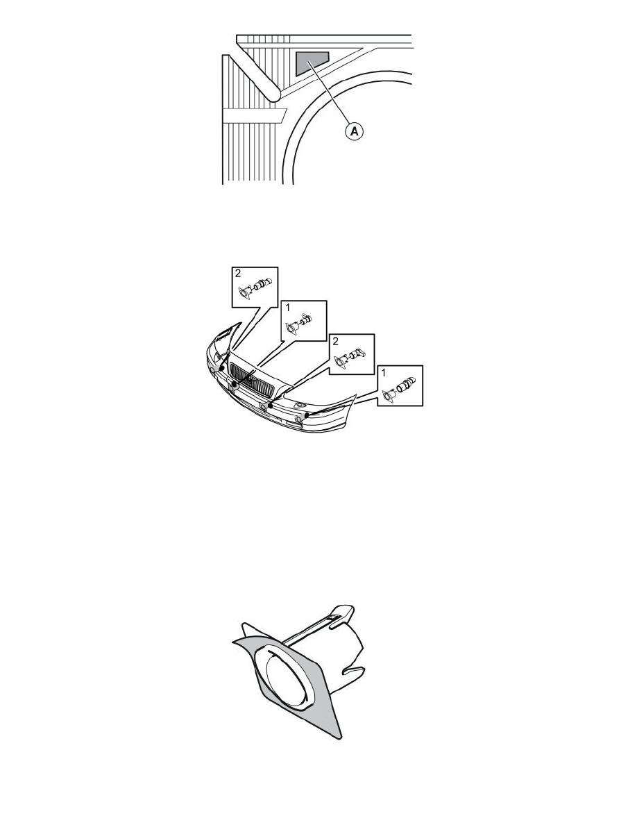
Check that the markings on the reverse (A) of the sensor holders are correctly positioned
-
The holders must be positioned in the following order, from left to right: 1, 2, 1, 2.
Illustration A
-
Remove the protective film from one side of the tape
-
Secure the tape on the sensor holder
-
Carry out the above procedure on the remaining three sensor holders
-
Cut away a piece of the collar on the holders for the inner sensor where it is turned in towards the centre of the bumper
-
Cut away a piece of the collar which is turned downwards on the holders for the outer sensors
-
Check the position of the holders. Place the sensors in the holders. The connectors for the inner sensors must be turned outwards.
Note! Check that the sensor holders can be installed before removing the backing tape.
Illustration B
-
Remove the protective film from the pieces of tape on the sensor holders
-
Install the holders for the sensors. The numbers must be pointing upwards so that they are horizontally in line with the bumper casing. See the
illustration.