
S60 2.4 L5-2.4L VIN 61 B5244S (2001)
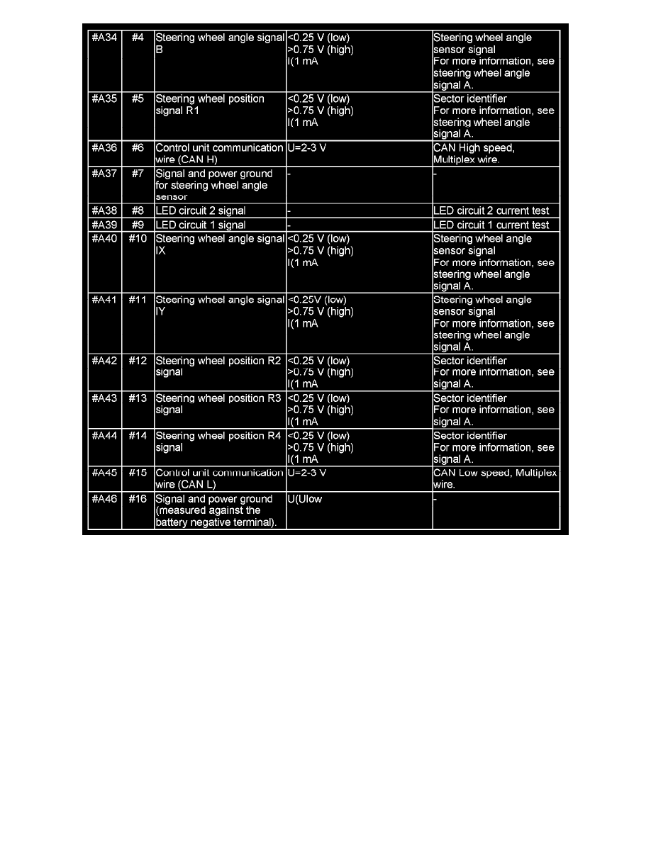
Signal Descriptions Table (Part 2 Of 2)
The values in the table represent the values between the connections shown in column 1 and #A46 (ground), unless otherwise stated in brackets.
Note: It is important that the test box is connected and the ground points checked before testing begins.
U = DC voltage (V)
I = amperage (A)
Ubat = battery voltage (V)
Ulow = voltage close to O V