
S60 2.4 L5-2.4L VIN 61 B5244S (2001)
For further information about signals and other values, see Signal specification. See: Signal Specification
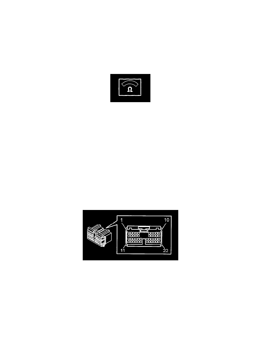
Checking the Power Supply and Ground Terminals, Permanent Fault
Checking power supply and ground terminals
Check steering wheel module connector A. Check for contact resistance and oxidation.
Check fuse 22 in the passenger compartment fusebox for the steering wheel module.
NOTE: If the fuse is blown, check the circuit after the fuse. Check for a short-circuit to ground before replacing the fuse. Then replace the fuse. For
further information about the circuit after the fuse, refer to the appropriate wiring diagram. See Diagrams/Electrical.
Check the cable for power supply between fuse 22 in the passenger compartment fusebox and the control module terminals # A1 and # A6. Check for an
open-circuit.
Check the ground lead between control module # A22 and ground terminal 31/84. Check for an open-circuit. Check ground terminal 31/84. Check for
contact resistance and oxidation.
Remedy as necessary.
Other information:
-
To access and replace the control module see Steering wheel module (SWM), replacing.
-
To access or replace the fuses, see Fusebox, Passenger Compartment, Replacing.
-
Checking Wiring and Terminals, Permanent Faults.
Was a fault detected?
YES/NO -
See:
Checking Power Supply and Ground Terminal, Intermittent Fault
Checking the Power Supply and Ground For The Control Module
Check steering wheel module connector A. Check for contact resistance and oxidation.
Check fuse 22 in the passenger compartment fusebox for the steering wheel module.
NOTE: If the fuse was blown, check the circuit after the fuse. Check for contact resistance and oxidation.
Check the cable for power supply between fuse 22 in the passenger compartment fusebox and the control module terminals # A1 and # A6. Check for an
open-circuit.
Check the ground lead between control module #A22 and ground terminal 31/84. Check for an open-circuit.
Check ground terminal 31/84. Check for contact resistance and oxidation.