
S60 2.4T L5-2.4L Turbo VIN 58 B5244T3 (2001)
Close the cover over the connector housing.
Ensure that the cover plate locks into the hinge catch properly.
C. Repairing connector housing
Remove the connector from the ABS module and open the cover.
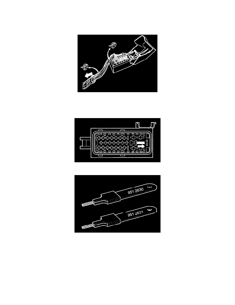
Cut the tie straps at the connector. Remove the protective sleeve and slide back as far as necessary to expose the cables. Tape back the protective sleeve.
(In some cases the protective sleeve may have been replaced by a corrugated, split plastic protective tube. If this is the case, cut the tape and remove the
protective tube.)
Disconnect the secondary lock for the cable terminal by pushing the catch (in the shaded area) in the direction of the arrow using a screwdriver.
Disconnect and transfer the cables to the new connector one at a time.
It is important to disconnect one cable at a time so as not to mix them up.
Use terminal removal tool 951 2630 for the small cavities and 951 2631 for the large ones.
CAUTION: To disconnect a cable push it in towards the connector while pressing the terminal removal tool in from the other side to release
the locking tabs on the cable terminal.