
S60 2.5T L5-2.5L Turbo VIN 59 B5254T2 (2006)
A collision signal is also sent to the phone module (PHM) and the central electronic module (CEM) via the Controller area network (CAN).
The supplemental restraint system module (SRS) decides to deploy the airbags and/or the seat belt tensioners in the event of a frontal collision. This
depends on information such as:
-
if the driver and front passenger are wearing seat belts or not
-
if there is a fault in the seat belt buckles
-
if there is a fault in the controller area network (CAN) communication.
As a result of the above conditions, in the event of a low impact collision the seat belt tensioner may deploy on the driver's side whilst the airbag is
deployed on the passenger side.
The SRS indicator lamp lights when the ignition is switched on. If no faults are registered by the control module, either internally or from the sensors,
wiring or igniters, a signal is transmitted on the controller area network (CAN) to the driver information module (DIM) confirming that the SRS indicator
lamp can be switched off. If there is a fault, the supplemental restraint system module (SRS) transmits information to the driver information module
(DIM) indicating which lamp should be lit and the text to be displayed in the combined instrument panel. The driver information module (DIM)
continuously transmits information to the supplemental restraint system (SRS) control module via the controller area network (CAN) about the status of
the SRS indicator lamp.
If the SRS indicator lamp stops working, the general warning lamp is used instead.
Note that after a collision, it may be necessary to replace the cable harness for the components of the collision protection system which have deployed.
This is because the connectors may melt at the moment of deployment. If a connector has melted, the cable harness adjacent to the connector must be
replaced.
WARNING: The battery must be disconnected before any work is carried out on the supplemental restraint system (SRS). Otherwise the
airbags could accidentally deploy.
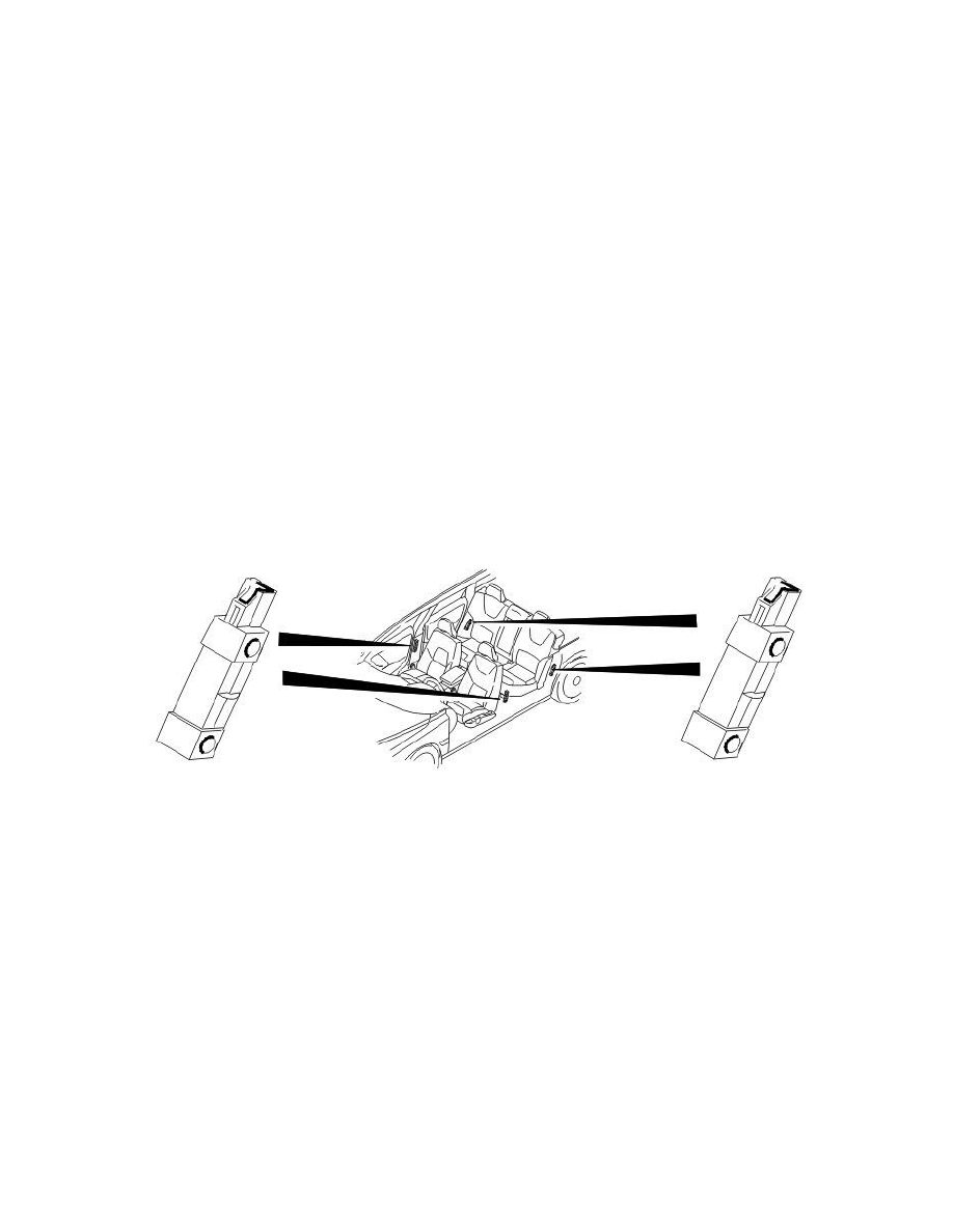
Side impact sensor
The side impact sensors in the vehicle are used to measure the collision pulses.
The four sensors which are used in the car are:
-
1 side impact sensor in each left and right B post
-
1 side impact sensor in each left and right C post.
The side impact sensors have integrated logic. In the event of a collision, they determine whether the impact was large enough to warrant transmitting an
activation signal to the control module to deploy the side impact airbag. Only the side impact protection on the side from which the activation signal was
sent can be deployed.
The side impact sensors transmit continuous signals to the control module to indicate that they are working. In the event of a fault in the side impact
sensor, a fault signal is transmitted to the control module which then stores a diagnostic trouble code (DTC). A diagnostic trouble code (DTC) is stored
when the communication between the control module and one of the side impact sensors does not function. Each side impact sensor has a software ID.
The ID is used to check that the correct side impact sensor is installed. This is because the activation level of the signal which is transmitted to the
control module is not necessarily the same for the different side impact sensors.
The front (B-post) and rear (C-post) side impact sensors are a different color and have different coding on their connectors to simplify installation.
The front side impact sensors cannot be installed in the position for the rear side impact sensors and vice versa.
Data is transmitted on the same cable used for power supply.