
S60 2.5T AWD L5-2.5L Turbo VIN 59 B5254T2 (2004)
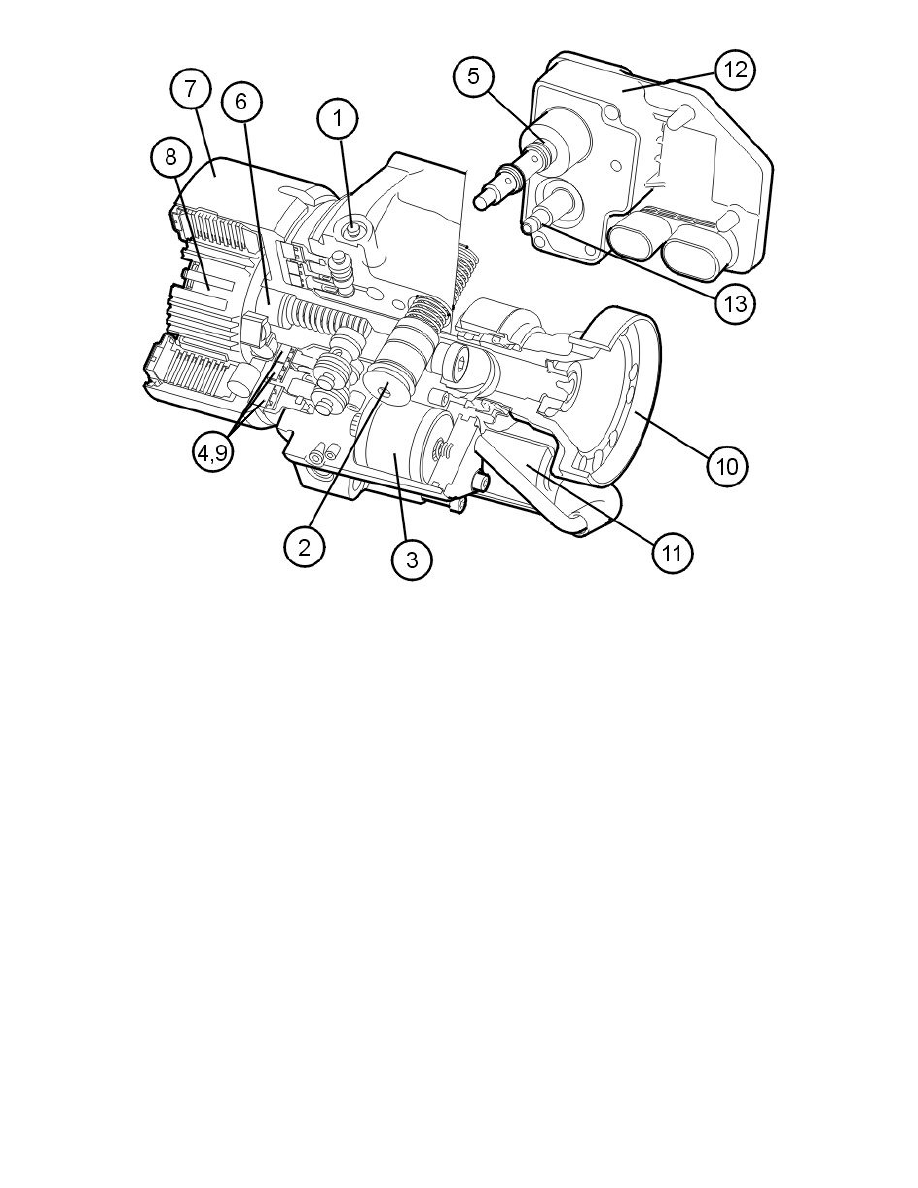
The hydraulic section consists of 1-5, the mechanical section consists of 6-10 and the electronic section consists of 11-13.
1. Pressure valves
2. Accumulator
3. Oil filter
4. Annular pistons
5. Control valve/axial solenoid
6. Input shaft
7. Inner and outer wet multi-plate clutch
8. Inner connection hub with sinusoidal cam disc
9. Rollers with annular pistons
10. Output shaft
11. Electrical feed pump
12. Differential electronic module (DEM)
13. Oil pressure and temperature sensor.
The differential electronic module (DEM) is integrated in the coupling unit.
The differential electronic module (DEM) communicates with other control modules using controller area network (CAN) communication.
There are internal diagnostics for the control module.
Signals
The table below summarizes the input signals to and output signals from the differential electronic module (DEM). The following illustration displays
the same information with the Volvo component designations.