
S60 AWD L5-2.5L Turbo VIN 59 B5254T2 (2005)
Suspension Control Module: Description and Operation
System Overview
System overview
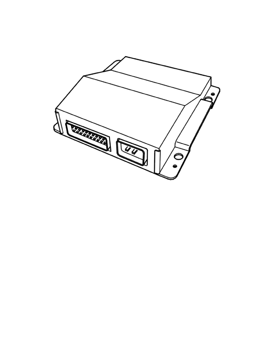
Control module
The main task of the suspension module is to manage the Four-C (Continuously Controlled Chassis Concept) function, i.e. continuously regulate the
damping in the shock absorbers. The control module is under the floor carpet on the left-hand side of the center console beside the gear selector lever.
The control module continuously reads the input signals to calculate the movements of the car and control the damping forces to keep the ride comfort
as good as possible. The Four-C function is a factory installed accessory only available on cars with DSTC (Dynamic stability and traction control).
The suspension module (SUM) reads off and controls directly connected components. The suspension module (SUM) communicates with other
control modules using serial communication.
The suspension module (SUM) checks activations and input and output signals via an integrated diagnostic system. if the control module detects a
fault, a diagnostic trouble code (DTC) is stored. However the control module continues to run the system in failsafe mode, where the shock absorbers
function as standard passive dampers. In the event of a fault, an error message is transmitted to the driver information module (DIM).
Any diagnostic trouble codes (DTCs) are stored in the memory in the suspension module (SUM). The data can be read off using VIDA.
An easy way to check whether the suspension module (SUM) is powered is to change driving mode and check that it changes. See Function, Changing
the driving mode.
If the voltage falls below 9 V or exceeds 16.0 V, the system continues in failsafe mode.
For further information, also see Signal specifications.
Signals
The table below summarizes the input signals to and output signals from the suspension module (SUM). The signal types are divided into directly
connected signals and CAN communication. The illustration below displays the same information with the Volvo component designations.