
S60 AWD L5-2.5L Turbo VIN 59 B5254T2 (2005)
The control module checks the input and output signals through an integrated diagnostic system. A diagnostic trouble code (DTC) is stored if the control
module detects a fault.
Any diagnostic trouble codes (DTCs) are stored in the control module memory. The data can be read off using VIDA.
The control module can process multiple collisions, frontal collisions, collisions from behind, side-on collisions and overturning.
The control module function can be easily checked by switching on the ignition. The SRS indicator lamp in the combined instrument panel must light up
when the key is in ignition positions I-III. The lamp goes out after a short while if no faults are detected. This means that the supplemental restraint
system (SRS) is functioning correctly.
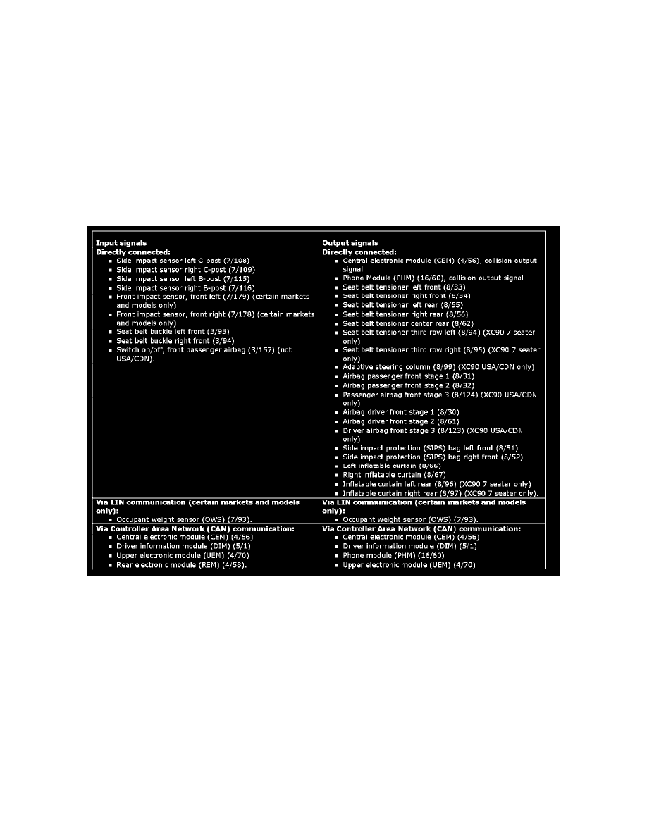
Signals
The table below summarizes the input signals to and output signals from the supplemental restraint system module (SRS). The signal types are divided
into directly connected signals, LIN and CAN communication. The illustration below displays the same information with the Volvo component
designations.