
S70 L5-2.4L VIN 61 B5244S (2000)
Hint: If fuse 6 has blown, fault-trace the circuit after fuse 6 for a short-circuit to ground according to Checking wiring and terminals - Permanent
faults, for further information about the circuit after the fuse, see the Wiring Diagrams.
Check circuit before fuse 6 for an open-circuit according to Checking wiring and terminals - Permanent faults. Check cable between fuse 6 and
VGLA control module #B1 for an open-circuit according to Checking wiring and terminals - Permanent faults. Check cable between VGLA control
module #A1 and ground for an open-circuit, according to Checking wiring and terminals - Permanent faults.
See: Diagnostic Trouble Code Tests and Associated Procedures/Related Tests and Information/Checking Wiring and Terminals - Permanent Faults
Other information:
-
The voltage between VGLA control module #B1 and ground should be battery voltage.
Remedy as necessary.
After performing this procedure See: Checking Communication With Control Module/Verification
Checking Communication Cable to Data Link Connector (DLC)
Checking Communication Cable To Data Link Connector (DLC)
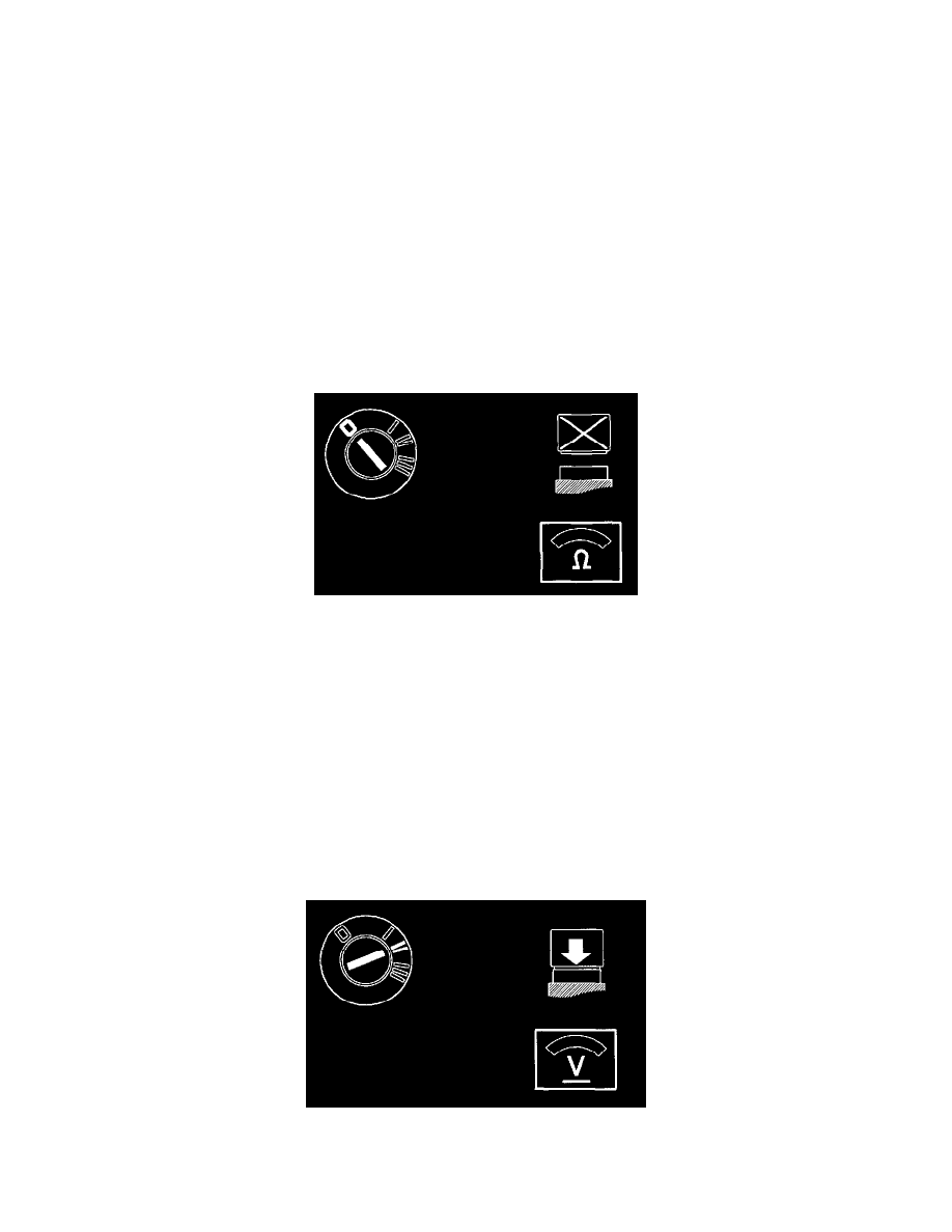
-
Ignition off.
-
VGLA control module disconnected.
-
Disconnect VCT 2000 from the data link connector (DLC).
Connect an ohmmeter between data link connector (DLC) terminal 7 and VGLA control module connector #B19.
The ohmmeter should read approximately 0 [ohm].
OK
-
See: Checking Communication With Control Module/Checking For an Open-Circuit
Not OK -
See: Checking Communication With Control Module/Checking the Communication Cable
Checking the Communication Cable
Checking The Communication Cable
-
Ignition off.
-
Connect control module.
-
Ignition on.