
S80 AWD V8-4.4L VIN 85 B8444S (2008)
-
a terminal with three pins
-
integrated electronics
-
2 capacitive gauge elements
-
a PTC resistor.
The sensor is supplied with 5 V from the engine control module (ECM) and generates a pulse width modulation (PWM) signal to the engine control
module (ECM).
The engine control module (ECM) can diagnose the sensor.
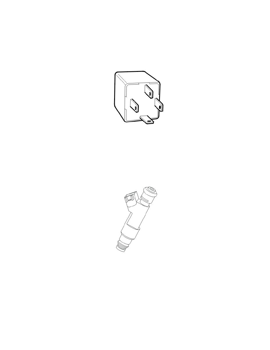
Main relay (system relay)
The function of the main relay (system relay) is to supply certain components with voltage.
The relay is mechanical and has a closing and opening function. In the rest position the circuit in the relay is open.
The main relay terminals (#30 and #86) are supplied with voltage by the battery. When the starter button on the start control module (SCU) has been
activated and the engine control module (ECM) is powered, the terminal (#85) on the main relay is grounded by the engine control module (ECM).
When the terminal (#85) is grounded, the relay is activated and a number of components are powered via the relay terminal (#87).
The main relay is in the integrated relay/fuse box in the engine compartment and is diagnosed by the engine control module (ECM).
Injectors
The function of the injectors is to spray fuel into the cylinders in the correct spray patterns. This happens sequentially.
The injectors are located under the intake manifold.
The engine control module (ECM) controls the injectors by grounding the valves in pulses.
The injectors can be diagnosed by the engine control module (ECM) and can be activated.
Ignition coils