
S80 AWD V8-4.4L VIN 85 B8444S (2008)
Variable intake system
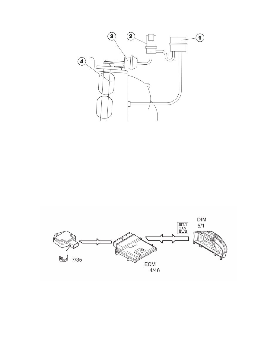
The variable intake system components consist mainly of:
1. Vacuum tank
2. Valve for variable intake
3. Vacuum motor
4. Throttle discs
In order to maintain a high volume of intake air at different engine speeds (RPM) and engine loads, B8444S is equipped with the Variable Intake
System. The Variable Intake System divides drawn in air into two volumes. The engine control module (ECM) then regulates the air flow between these
volumes using dampers in order to achieve the optimum air flow at specific operating temperatures.
The vacuum from the engine is stored in a vacuum tank (1). The vacuum is then guided to the vacuum motor (3) using the variable intake valves (2). The
vacuum motor affects the damper in the intake system.
The variable intake valve is controlled by the engine control module (ECM) (4/46).
The variable intake valve can be activated and the variable intake function can be diagnosed by the engine control module (ECM).
Oil monitoring
General
The following components are used for oil monitoring:
-
oil level-/oil temperature sensor (7/35)
-
engine control module (ECM) (4/46)
-
driver information module (DIM) (5/1).
The sensor informs the driver via the driver information module (DIM) that the oil needs to be topped up.
Detecting the oil level
The integrated electronics of the sensor calculates the oil level using the measured value for the oil temperature.
For the correct oil level to be calculated, temporary oil level changes in the oil trough must also be included in the calculation, which can occur when
driving on hills, around bends or similar for example. The engine control module (ECM) makes these calculations using the oil level sensor signal and a