
S80 AWD V8-4.4L VIN 85 B8444S (2008)
Some control modules, such as the engine control module (ECM), the electronic throttle module (ETM), the anti-lock brake system module (ABS) and
the transmission control module (TCM) continually check the existence of each other and store diagnostic trouble codes (DTCs) in the event of missing
signals. These diagnostic trouble codes (DTCs) are often due to different driving conditions and combinations of diagnostic trouble codes (DTCs) are
often stored which can make fault-tracing more difficult. When attempting to recreate the fault, there is no guarantee that the same combination of
diagnostic trouble codes (DTCs) will be stored. The detection of these diagnostic trouble codes (DTCs) is often more sensitive and they are usually
stored more easily than CEM-1A51 to CEM-1A66 or CEM-DF03 to CEM-DF16. This can therefore be an indication of a short-term intermittent fault
having occurred on the CAN network.
Below is a selection of diagnostic trouble codes (DTCs) that may or may not be stored in the event of an intermittent fault on the CAN network:
-
ECM-928C (Bosch), ECM-922A (Denso), only when the engine is running. These diagnostic trouble codes (DTCs) indicate that the control signal
for the cruise control is missing or could not be received by the engine control module (ECM)
-
ECM-901A, ECM-901E, ECM-902A, ECM-911A, ECM-912A and ECM-913A for Bosch and ECM-901A, ECM-902A, ECM-911A, ECM-912A
for Denso
-
SRS-00D6, time-out for the seat belt buckle. This diagnostic trouble code (DTC) indicates that the supplemental restraints system module (SRS)
has not received the status of the seat belt buckles from the central electronic module (CEM). The sensor for the seat belt buckles is directly linked
to the central electronic module (CEM)
-
SRS-00D5, status of the SRS indicator lamp in the driver information module (DIM)
-
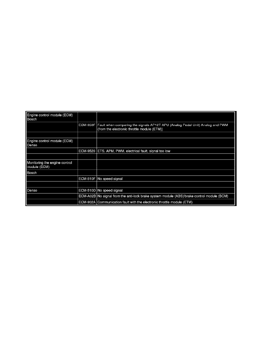
Discrepancies in the signal from the pedal position sensor between the directly connected signal and the signal over the CAN network. See the
table below.
Part 2
Information about the CAN network, structure and function (Continued)
Multiple diagnostic trouble codes (DTCs) and extended diagnostics (counters and freeze frames)
The detection time for faults in the CAN network varies depending on the diagnostic trouble code (DTC). This means that for different fault occurrences,
different diagnostic trouble codes (DTCs) can be stored in different control modules. Several diagnostic trouble codes (DTCs) in different control
modules can be confusing and must be investigated at the start of fault-tracing to check for any link between the various codes.
It is now possible to read off extended diagnostic trouble code (DTC) information in VIDA, normally counters and frozen values. This can also help with
fault-tracing on the CAN network as it can provide information about diagnostic trouble codes (DTCs) that are stored simultaneously. Remember that the
function using counters can be implemented differently in different control modules, which can make it difficult to compare cycles between different
control modules.
When performing fault-tracing on a car with many intermittent E003 and CEM-1A51 to CEM-1A66 diagnostic trouble codes (DTCs), this can be made
easier by checking the affected control modules. Copy the diagram, Data communication for the relevant car model, and write down all diagnostic
trouble codes (DTCs) and counters at the relevant control modules. Check any conclusions can be drawn from where the diagnostic trouble codes
(DTCs) are stored. If the diagnostic trouble codes (DTCs) are in control modules at one end of the CAN network, this can give an indication of where
the fault may be located.
Limp-home modes and characteristics of control modules in the event of faults in the CAN network
When a control module cannot receive messages from the central electronic module (CEM) it will go into Limp-home mode. In such cases, the control
module can retain part of its functionality. The remaining functionality varies in different control modules. If a fault occurs after a control module has