
S80 T6 L6-2.9L Turbo VIN 91 B6294T (2002)
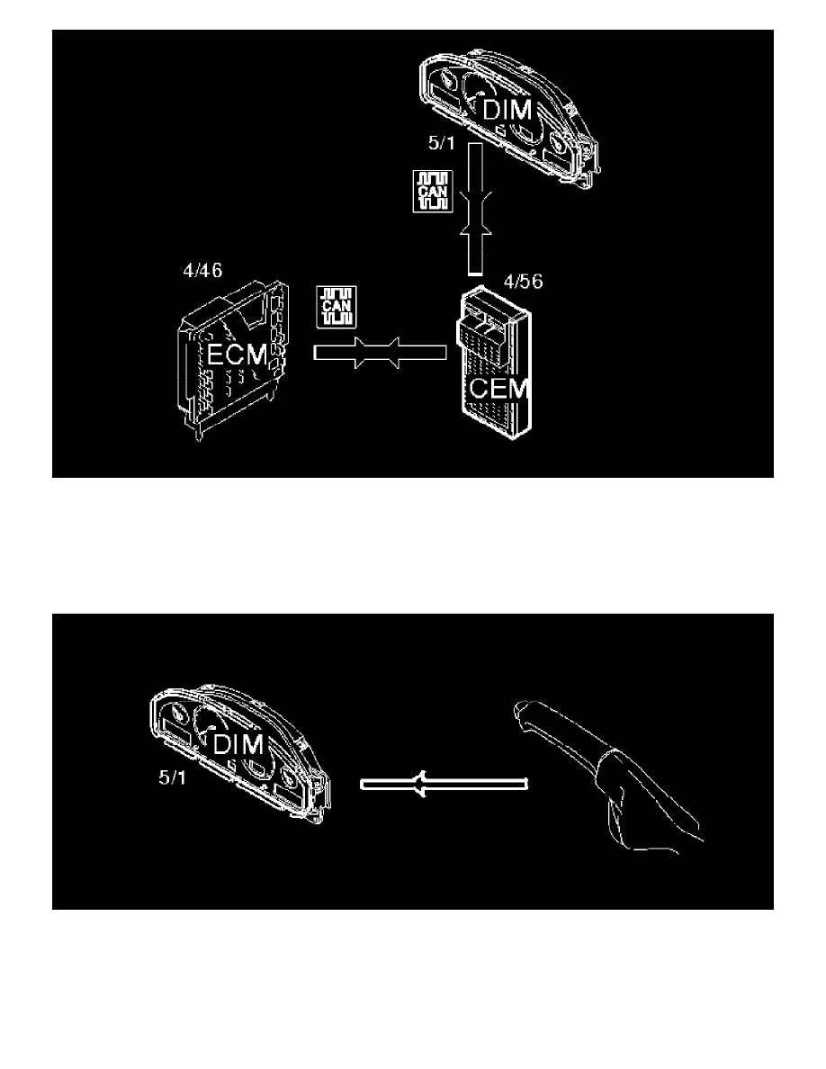
The engine control module (ECM), (4/46) processes the value from the coolant temperature sensor (7/16). The processed value is then transmitted to the
central electronic module (4/56) on the high speed section of the Control Area Network (CAN). The central electronic module receives the signal and
generates a corresponding signal on the low speed section of the Control Area Network (CAN). The driver information module (5/1) reads the signal
from the low speed section of the Control Area Network (CAN). The driver receives information about the temperature from the engine coolant
temperature gauge in the combined instrument panel. If the value is too high a red lamp lights and a text message is displayed outlining the fault.
Parking brake
A switch is connected to the combined instrument panel (driver information module) (5/1) which detects the incoming signal indicating whether the
parking brake is applied or not. The switch is activated and the lamp is lit when the parking brake is applied. This signal is directly connected.
SRS lamp