
S80 T6 L6-2.9L Turbo VIN 91 B6294T (2002)
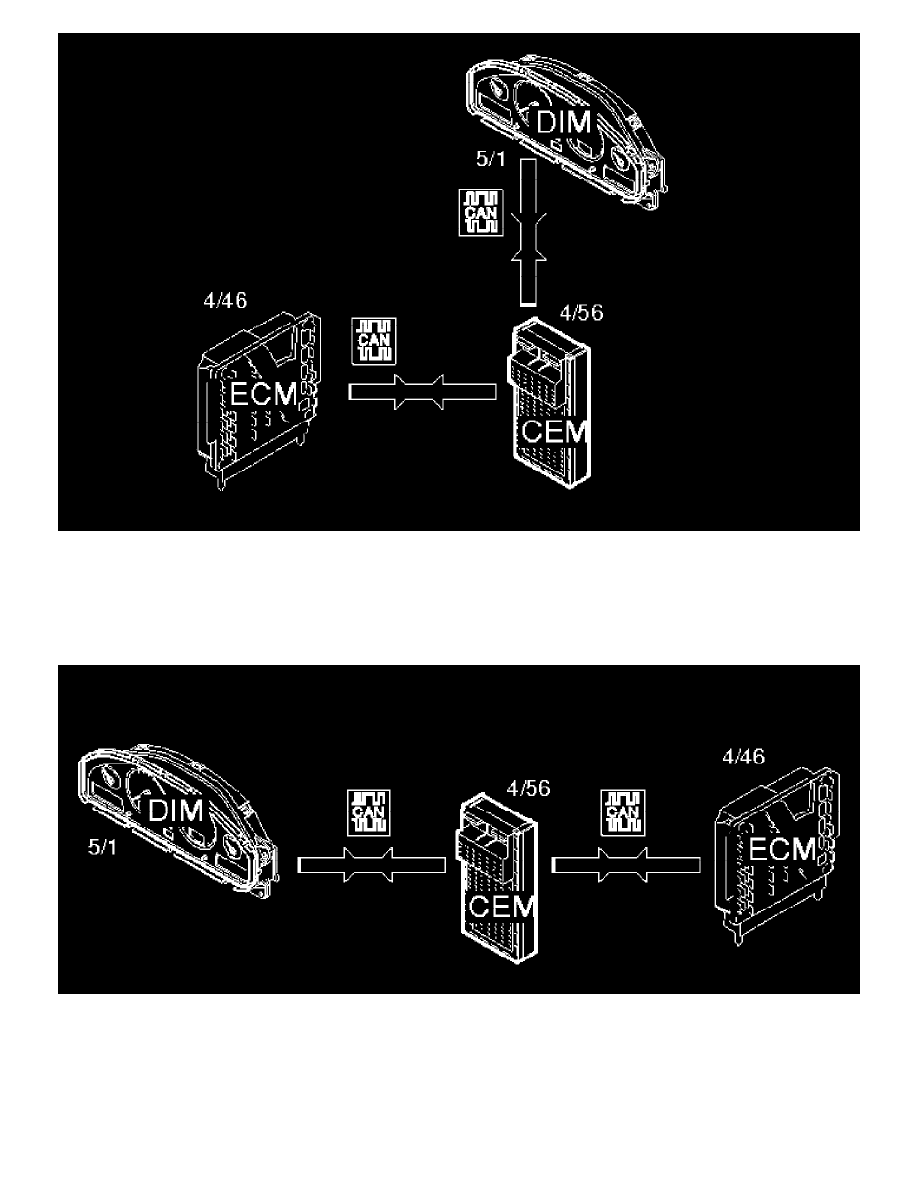
A flywheel sensor (7/25) is connected to the engine control module (ECM) (4/46). The engine control module (ECM) transmits the engine speed signal
onwards via the high speed section of the Control Area Network (CAN). The central electronic module (4/56) receives the signal and generates a
corresponding signal on the low speed section of the Control Area Network (CAN). The driver information module (5/1) reads the signal from the low
speed section of the Control Area Network (CAN). The driver information module receives the value and presents the actual engine speed for the driver.
Lamp for low oil pressure
The oil pressure sensor (7/6) is connected to the engine control module (ECM) (4/46). The engine control module transmits the oil pressure signal
onwards via the high speed section of the Control Area Network (CAN). The central electronic module (4/56) receives the signal, and generates a
corresponding signal on the low speed section of the Control Area Network (CAN). If the oil pressure is low, the driver information module (5/1) reads
the signal from the low speed section of the Control Area Network (CAN). The driver information module indicates this to the driver by lighting a red
warning lamp and displaying a text string with explanatory information.
General warning lamp
The function is to display different "faults" in the car. When a lamp lights this is followed by a text message which presents the driver with additional