
S80 T6 L6-2.9L Turbo VIN 91 B6294T (2002)
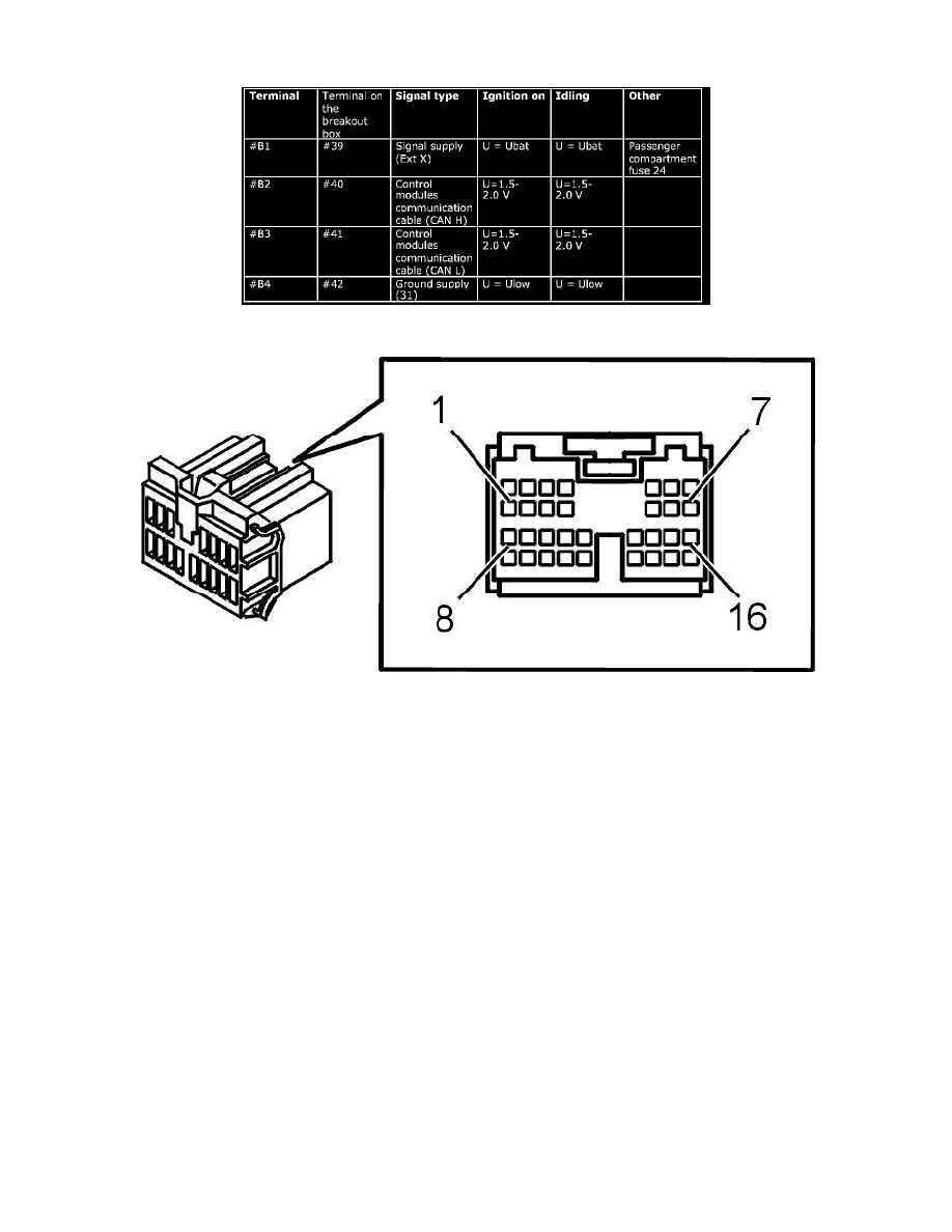
Terminals B1-B4 correspond to terminals 39-42 on the breakout box.
Input signals from the control panel Connector, green (16- pin)
Before taking any readings, read Signal specification, Power seat module: Connecting the breakout box and checking the ground terminals.
Terminals C1-C16 correspond to terminals 25-40 on the breakout box.