
S80 T6 L6-2.9L Turbo VIN 91 B6294T (2002)
Tail Lamp: Testing and Inspection
Checking the Rear Position Lamp
Checking the rear position lamp
Checking fuses and wires
Check that the fuses 11C/30 (group 1) and 11C/31 (group 2) respectively in the interior are intact.
For group 1, check the wires between:
-
fuse 11C/30 and shunt 20/28
-
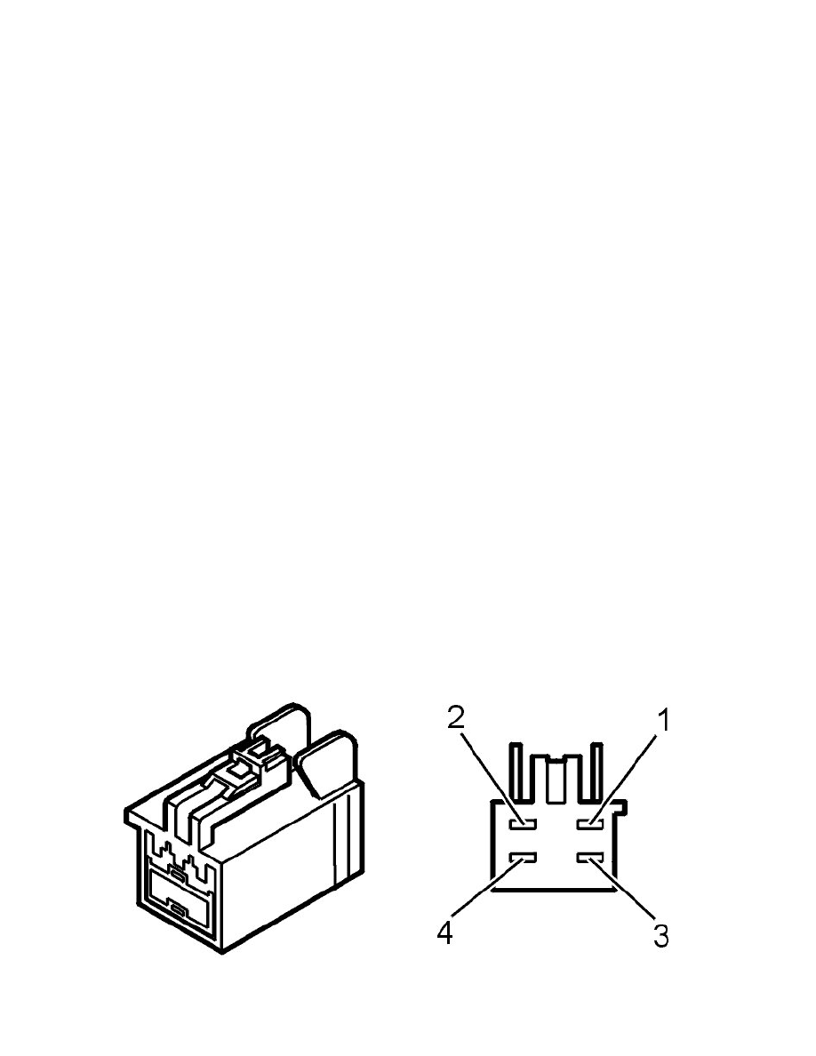
shunt 20/28 and left or right lower lamp body 1 (in boot)
for an open circuit as described in Checking wiring and terminals. Permanent fault See: Powertrain Management/Computers and Control
Systems/Testing and Inspection/Diagnostic Trouble Code Tests and Associated Procedures/Related Tests, Information and Procedures/Checking Wiring
and Terminals. Permanent Fault , and for a short circuit to ground as described in Checking wiring and terminals. Permanent fault See: Powertrain
Management/Computers and Control Systems/Testing and Inspection/Diagnostic Trouble Code Tests and Associated Procedures/Related Tests,
Information and Procedures/Checking Wiring and Terminals. Permanent Fault.
For group 2, check the wires between:
-
fuse 11C/31 and shunt 20/33
-
shunt 20/33 and left or right lower lamp body 2 (in boot)
for an open circuit as described in Checking wiring and terminals. Permanent fault See: Powertrain Management/Computers and Control
Systems/Testing and Inspection/Diagnostic Trouble Code Tests and Associated Procedures/Related Tests, Information and Procedures/Checking Wiring
and Terminals. Permanent Fault , and for a short circuit to ground as described in Checking wiring and terminals. Permanent fault See: Powertrain
Management/Computers and Control Systems/Testing and Inspection/Diagnostic Trouble Code Tests and Associated Procedures/Related Tests,
Information and Procedures/Checking Wiring and Terminals. Permanent Fault.
Regardless of the group, also check the ground wires between the left or right lower lamp housing 4 (in the boot) and the ground point for an open circuit
as described in Checking wiring and terminals. Permanent fault See: Powertrain Management/Computers and Control Systems/Testing and
Inspection/Diagnostic Trouble Code Tests and Associated Procedures/Related Tests, Information and Procedures/Checking Wiring and Terminals.
Permanent Fault.
Check the control unit connector B1 and lock unit connector 6 for contact resistance and oxidation as described in Checking wiring and terminals.
Permanent fault See: Powertrain Management/Computers and Control Systems/Testing and Inspection/Diagnostic Trouble Code Tests and Associated
Procedures/Related Tests, Information and Procedures/Checking Wiring and Terminals. Permanent Fault and check the intermediate wire for an open
circuit as described in Checking wiring and terminals. Permanent fault See: Powertrain Management/Computers and Control Systems/Testing and
Inspection/Diagnostic Trouble Code Tests and Associated Procedures/Related Tests, Information and Procedures/Checking Wiring and Terminals.
Permanent Fault.
Do the necessary corrective action.
Additional information
-
To access relay/fuse box in the boot, see Integrated relay/fusebox cargo compartment/Rear electronic module (REM), replacing See:
Maintenance/Fuses and Circuit Breakers/Fuse Block/Service and Repair/Integrated Relay/Fusebox Cargo Compartment/Rear Electronic Module
(REM), Replacing.
-
To access the interior fuse box, see Fusebox, passenger compartment, replacing See: Maintenance/Fuses and Circuit Breakers/Fuse Block/Service
and Repair/Fusebox, Passenger Compartment, Replacing.