
S80 T6 L6-2.9L Turbo VIN 91 B6294T (2002)
Engine Control Module: Description and Operation
Design
Part 1
Design
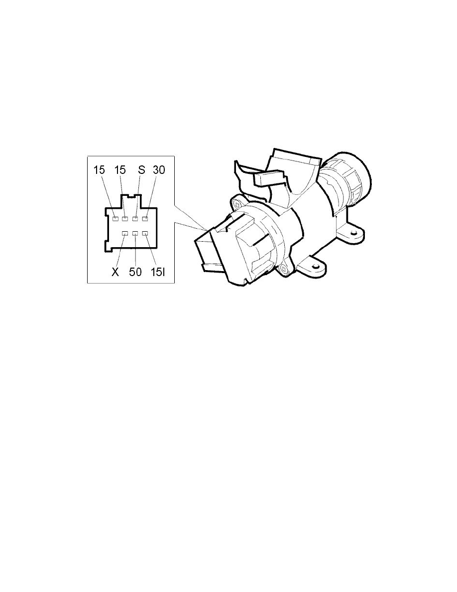
Ignition switch
The Engine Control Module (ECM) uses the signal from the ignition switch to detect when the ignition key has been turned to position II or III. When
the key is in the ignition position (position II) or starting position (position III) a high signal (Ubat) is transmitted from the ignition switch to the engine
control module (ECM). The engine management system prepares for start-up (for example, temporarily activates the fuel pump (FP) relay). When the
flywheel in the engine rotates, the engine speed (RPM) sensor signal is used to keep the fuel pump (FP) relay activated.
The fuse in the fusebox in the passenger compartment supplies current to the ignition switch.
The central electronic module (CEM) can diagnose the ignition switch.
Brake lamp switch