
S80 T6 L6-2.9L Turbo VIN 91 B6294T (2002)
control module (ECM) and the signal that varies depending on the position of the brake pedal is sent to the engine control module (ECM).
When the pedal is released the signal is 3 - 4.5 V, the precise value depends on the engine control system in the vehicle. The reason that the signal differs
between different engine control systems, despite it being the same sensor, is that the control module's internal circuits differ, which affects the signal
level from the sensor. When the pedal is depressed, the voltage from the sensor drops.
From model year 2002 the brake pedal position sensor is directly connected to the brake control module (BCM), information is sent over the CAN to the
Engine control module (ECM).
The information from the brake pedal position sensor is used:
-
together with information from the stop lamp switch to determine when it is permitted to use cruise control
-
to determine whether the information from the stop lamp switch is valid or not.
To determine whether the information from the stop lamp switch can be used or not, the Engine control module (ECM) and the Electronic throttle
module (ETM) carry out an electrical check of the circuits and plausibility checks.
For further information about which tests are carried out, see diagnostic trouble code (DTC) information for the relevant diagnostic trouble code (DTC).
Accelerator pedal (AP) position sensor
The accelerator position sensor is mounted by the pedal box in the passenger compartment and makes a mounting for accelerator pedal. Its main task is
to supply the Engine control module (ECM) with information about the position of the accelerator pedal.
The accelerator pedal position sensor consists of two internal sensors, where one generates an analog signal and the other a pulse width modulated signal
(PWM). The purpose of having two types of sensor is to eliminate the probability of a fault from both signals from the sensors being incorrect, at the
same time as them showing the same pedal position and the control module considers them correct.
The analog sensor supplies the Engine control module (ECM) with a signal that is approximately 0.5 V when the pedal is released and approximately 4.5
V when fully depressed. The sensor receives a voltage supply (5 V) and ground from the Engine control module (ECM).
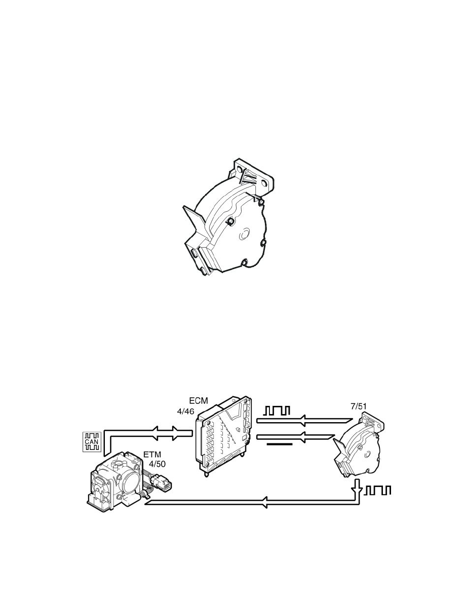
The pulse width modulated (PWM) sensor supplies both the Engine control module (ECM) and Electronic throttle module (ETM) with a signal that has
a fixed frequency of approximately 200 Hz where the pulse ratio varies between 8-88 %, depending on the position of the accelerator pedal.
The sensor receives voltage supply (12 V) via the main relay and is grounded via its own ground terminal. the signal to the Electronic throttle module
(ETM) is electrically routed via the Engine control module (ECM), however, without affecting the signal at all.
The Engine control module (ECM) first uses the analog signal from the accelerator position sensor to calculate the desired throttle angle. The Engine
control module (ECM) then transmits this request about the desired throttle angle via the CAN to the Electronic throttle module (ETM), which then
fulfils the desired throttle angle and transmits back the information about the current throttle angle.
The pulse width modulated signal is used to monitor the analog signal. If there is a fault in the analog signal, the system uses the pulse width modulated
(PWM) signal instead.
There are also situations when the PWM signal is used to control the throttle angle without a fault being detected on the analog signal. For example,