
S80 T6 Executive L6-2.8L Turbo VIN 90 B6284T (2001)
-
when the driver depresses the "0" button on the steering wheel
-
if "P" or "N" positions are transmitted on the Controller area network (CAN) (applies to automatic transmissions)
-
if the speed deviates too much from the set value
-
when certain diagnostic trouble codes (DTCs) are stored which do not allow continued activation (For further information see diagnostic trouble
code (DTC) information).
Air flow adaptation (Only turbo and 6 cylinder non turbo engines)
Note! This section regards the air flow adaptation over the throttle unit, not to be confused with the control module's fuel adaptation (lambda
adaptation).
There is a correction factor in the Engine control module (ECM) for adjusting the leakage flow over the throttle unit. Leakage flow means the air that
does not go through the throttle unit, but goes via the crankcase ventilation, power brake booster and EVAP system. For the control module to be able to
learn the adjustments needed in the different air flow areas, there are two adaptation areas. One for idling and one for part load. These values are saved
when the engine is switched off.
These values can be read off using the "Air mass, correction value" and "Leakage flow over throttle unit" parameters.
Air leakage flow via throttle unit
Hint: The following measurement for diagnostic trouble code (DTC) ECM-130A can be carried out to determine the fault cause.
Air flow adaptation idling
The parameter for air flow adaptation idling is one of the parameters for determining the leakage flow over the throttle unit where the mass air flow
(MAF) sensor flow determines the reference value. The adaptation value is the value that must be added or subtracted from the control module calculated
air flow. The calculated air flow added or subtracted from the adaptation value should be the same as the mass air flow (MAF) sensor's flow.
The adaptation value is not used as a part of a diagnostic function and will not, in the event of a large value, result in a diagnostic trouble code (DTC).
The value can be used to evaluate the air flow over the throttle unit. The adaptation value is displayed in kg/h and the normal values are 5-10 kg/h.
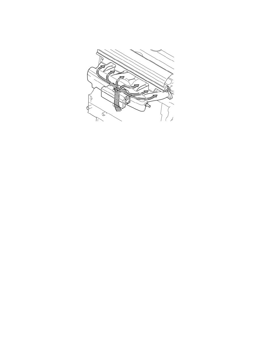
The engine does not only obtain air via the throttle unit, but also from the crankcase ventilation, the EVAP system and power brake booster for example.
The total of this air supply should give us our normal adaptation value of 5-10 kg/h, which does not pass through the throttle unit and therefore the mass
air flow (MAF) sensor.
If this air supply is removed or slightly restricted, e.g. if the crankcase ventilation becomes blocked, the adaptation value drops to less than 5 kg/h. Dirt in
the throttle unit can have the same effect and generally depends on the crankcase ventilation being blocked. The crankcase ventilation should, in such
cases, be checked first. If there is an air leak in the intake manifold the value would increase to above 10 kg/h.
Air flow adaptation part load
This is the part of air flow adaptation that makes it possible to compensate for the tolerance interval between different engines and for aging components.
The normal value without adaptation is 1. A value below 1, e.g. 0.95 indicates that more air passes through the mass air flow (MAF) sensor than
calculated. An indication of a blocked crankcase ventilation is a low adaptation value around 0.85 or less.
A value greater than 1 can indicate an air leak inside the intake manifold where, for example, a loose or defective vacuum line can give a value of 1.15 or
greater.
Diagnostic trouble code (DTC) ECM-130A is stored if the value for the air flow adaptation at part load and the correction factor are extremely large.
Unfortunately, the correction factor cannot be displayed in VIDA, but if this DTC has been generated, the correction factor can be assumed to be
extremely large. These adaptations should not only be used for fault-tracing, but considered to be an indication of which method should be used next
time.