
V40 L4-1.9L Turbo VIN 25 B4204T2 (2000)
Hydraulic Control Assembly - Antilock Brakes: Procedures
Replacing The ABS Hydraulic Modulator And Control Module
Note: For service work, the modulator is supplied with the control module. The secondary modulator circuit is filled with brake fluid. The circuit is
internally bled so that the brake system can be bled in the normal way after assembly.
Removal
Preparations
Ignition off.
Removing the control module
Note: Clean the modulator thoroughly
Note: Put rags under the modulator to prevent brake fluid spilling onto painted surfaces.
-
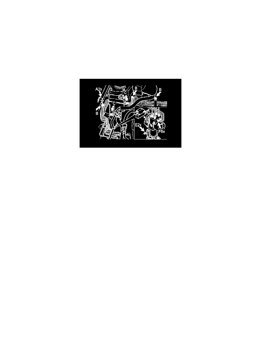
Remove the first three mounting clamps (B) for the brake pipes on the fender liner and cowl panel
-
Disconnect the brake pipes (F) on the modulator
-
Collect the brake fluid
-
Plug the pipes
-
Detach the hoses (A) on the fender liner at the modulator
-
Detach the reservoir (C) for the power steering system. Leave the reservoir hanging from the hose.
-
Separate the control module connector by pulling out the locking arm (D)
-
Remove the 2 nuts (E) holding the modulator
-
On diesel engines the engine control module (ECM) can be detached and lifted to the side.
Release the hydraulic modulator and the control module
Note: Be careful with the brake pipes and the pump motor cable positioned under the hydraulic modulator.
-
Lift the brake pipes past the bracket for the fluid reservoir
-
Carefully lift the hydraulic modulator
-
Locate the 3 rubber dampers and the 2 mounting lugs.
Installation
Installing the hydraulic modulator and the control module