
V40 L4-1.9L Turbo VIN 25 B4204T2 (2000)
Carefully mark the valve lifters so that exact reinstallation can be carried out, for example:
-
Intake side: I1, I2, I3 through I8
-
Exhaust side: Al, A2, A3 through A8.
Repeat the procedure for measuring the valve clearance for all cylinders on both the intake and exhaust sides. See Checking valve clearance, refer
to Testing and Inspection, Procedures.
Note! For tightening torques not in the text, refer to Specifications, Mechanical.
Installing the valve lifters and camshafts
Lubricate the valve guide wells.
Install all the valve lifters.
Note! Make sure that the lifters are in the same position as before.
Lubricate the camshaft bearing seats.
Install the intake camshaft. Ensure that the groove at the rear edge of the camshaft is above an imaginary center line.
Position the exhaust camshaft. Ensure that the groove at the rear edge of the camshaft is below an imaginary center line.
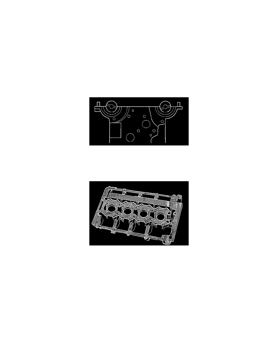
Applying liquid gasket
Wipe the oil film off the mating surfaces on the camshaft cover and cylinder head.
Install new O-rings around the spark plug wells on the cylinder head.
Apply liquid gasket 116 1059, or equivalent, to the camshaft cover.
Use roller 9S1 2767.
The surface must be completely covered without any excess.
Note! Ensure that no liquid gasket gets into the coolant or oil ducts. Only a thin layer of liquid gasket is required.
Installing the camshaft cover