
V40 L4-1.9L Turbo VIN 25 B4204T2 (2000)
Take a new measurement according to Valve clearance, checking See: Valve Clearance, Checking.
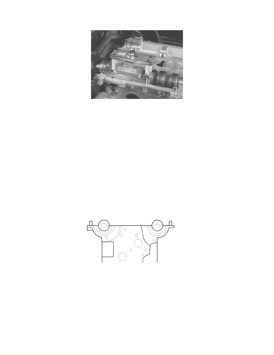
When the correct valve clearance is reached
Remove:
-
press tool 999 5765 Holder camshaft See: Tools and Equipment/999 5765 Holder Camshaft
-
the camshaft
-
the valve lifters.
Carefully mark the valve lifters so that exact reinstallation can be carried out, for example:
-
Intake side: I1, I2, I3......I8
-
Exhaust side: A1, A2, A3......A8.
Repeat the procedure for measuring the valve clearance for all cylinders on both the intake and exhaust sides. See Valve clearance, checking See: Valve
Clearance, Checking.
Note! For tightening torques not in the text, see Tightening torques for 4-cylinder gasoline engines See: Engine, Cooling and
Exhaust/Engine/Specifications/Mechanical Specifications/Tightening Torque.
Installing the valve lifters and camshafts
Lubricate the valve guide wells.
Install all the valve lifters.
Note! Make sure that the lifters are in the same position as before.
Lubricate the camshaft bearing seats.
Install the intake camshaft. Ensure that the groove at the rear edge of the camshaft is above an imaginary center line.
Position the exhaust camshaft. Ensure that the groove at the rear edge of the camshaft is below an imaginary center line.
Applying liquid gasket