
V50 L5-2.4L VIN 39 B5244S7 (2005)
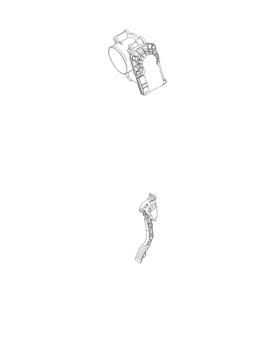
Electronic throttle unit
The electronic throttle unit, using the control signal from the engine control module (ECM), regulates the amount of air for engine combustion. This is
done using an electronic shutter.
The electronic throttle unit consists of a round throttle disc on a shaft. This is turned using a DC motor (damper motor), gear wheel and two springs, an
opening spring and a return spring. The damper motor is controlled by the control module and is supplied with powered by a built in power stage in the
control module. At one of the limit positions the throttle disc is closed so that no air can pass the throttle unit. At the other limit position the throttle disc
is parallel to the air flow so that the air is able to freely pass through the throttle unit. The throttle spindle is electronically monitored by two throttle
position (TP) sensors (Hall sensors) which are supplied with power by the control module. The signals from the throttle position (TP) sensors provide the
control module with data about the position of the throttle disc. The throttle unit also has a connector with six pins.
The electronic throttle unit is located on the engine intake manifold. In the event of a fault, the throttle unit must be replaced as a single unit.
The engine control module (ECM) can diagnose the electronic throttle unit.
Throttle position (TP) sensor
See: Electronic throttle unit
Accelerator pedal (AP) position sensor
The function of the accelerator pedal (AP) position sensor is to provide the engine control module (ECM) and central electronic module (CEM) with
information about the position of the accelerator pedal. This data is used by the engine control module (ECM) to deploy the shutter in the throttle unit to
the correct angle.
The sensor consists of a plastic housing with circuits. The output signals are a pulse width modulated (PWM) signal and an analog signal related to the
accelerator pedal (AP) position.
These signals indicate the position of the accelerator pedal (AP). The pulse width modulation (PWM) signal is transmitted to the engine control module
(ECM). The analog signal is transmitted to the central electronic module (CEM) and on to the engine control module (ECM) via the controller area
network (CAN).
Normally the pulse width modulation (PWM) signal is used to regulate the throttle angle. In the event of a fault in the pulse width modulation (PWM)
signal the analog signal is used as a replacement, unless this is also diagnosed as faulty.
The sensor is supplied with 12 V by the system relay via a fuse and is grounded in the car body.
The pulse width modulation (PWM) signal is also used in conjunction with the analog signal for accelerator pedal (AP) position sensor diagnostics. The
accelerator pedal (AP) position sensor signals can be read using VIDA. A diagnostic trouble code (DTC) is stored if the engine control module (ECM)
detects a difference between the analog and pulse width modulation (PWM) signals. The engine control module (ECM) then uses the signal with the