
V50 L5-2.4L VIN 39 B5244S7 (2005)
-
Checking wiring and terminals See: Testing and Inspection/Component Tests and General Diagnostics/Checking Wiring and Terminals
Continue - Fault-tracing information
------------------------
Checking communication errors, car model V70 (-00), V70 XC and S70/C70
Hint: Test the communication with another corresponding vehicle to decide if the malfunction is in the vehicle or in VIDA/VCT/cable harness. If the
communication works on another vehicle, the malfunction is in the vehicle.
Hint: For current information about each circuit and signals, see wiring diagram and signal description for each system.
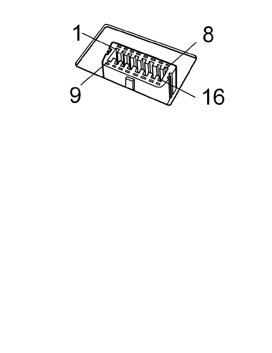
Diagnostic outlet
-
Check the voltage feed to diagnostic outlet #16. The voltage shall match battery voltage.
-
Check the cable for power ground and signal ground to diagnostic outlet #4 and #5.
Hint: When VCT2000 is connected to the diagnostic outlet (is supplied with voltage), the indicator diode shall be activated with a green light. Then the
indicator diode flashes quickly when communication takes place with a control module. In case of certain internal malfunctions on VCT2000 the
indicator diode is activated with a red light!
Communication cables
-
Check the communication cable (k-line) between diagnostic outlet #7 and the driver information module (DIM) #B4 and other connected control
modules for open circuit, short-circuit to ground and short-circuit to voltage.
Caution! In case of malfunction on this communication cable, communication cannot be established on the high-speed network. First
when communication takes place on this cable, the high-speed cables between the diagnostic outlet and driver information module (DIM)
are connected to the high-speed network in the vehicle. This is controlled via a relay in the driver information module (DIM).
-
Check communication cables between diagnostic outlet #6/#14 and the driver information module (DIM) #A19/#A20 for open circuit,
short-circuit to ground and short-circuit to voltage according to references above.
-
Also check the communication cables for thehigh-speed networkbetween the driver information module (DIM) and the other connected control
modules according to troubleshooting above.
Communication cable for cruise control as own system (not integrated)
-
Check the communication cable between diagnostic outlet #13 and cruise control for open circuit, short-circuit to ground and short-circuit to
voltage according to references above.
Communication cable for engine management system Fenix 5.2
-
Check the communication cable between diagnostic outlet #3 and engine control module (ECM) for open circuit, short-circuit to ground and
short-circuit to voltage according to references above.
Control modules
-
Check that the control module's voltage feed and ground connection are trouble-free.
Caution! Model year 99- and control modules on the CAN-network. If none of the above checks help, try reading out diagnostic trouble codes
in the driver information module (DIM). Done via VIDA vehicle communication. A prerequisite for being able to communicate with the control