
V50 L5-2.4L VIN 39 B5244S7 (2005)
-
the left-hand cargo compartment side panel. See: Side panel loadspace See: Body and Frame/Interior Moulding / Trim/Trim Panel/Service and
Repair/Side Panel Loadspace Side panel loadspace See: Body and Frame/Interior Moulding / Trim/Trim Panel/Service and Repair/Side Panel
Loadspace
-
the floor support spacer, 4 clips
-
the connectors
-
the 2 M6 screws
-
the subwoofer module (SUB).
Installation
Note! For tightening torques, see Specifications. See: Specifications/Mechanical Specifications/Starting and Charging
Installing subwoofer module (SUB)
Install:
-
the subwoofer module (SUB)
-
the 2 M6 screws.
Note! Check that there is no dirt in the optical connectors. The bend radius of the optic cables must not be less than 25 mm.
Install:
-
the connectors
-
the floor support spacer, 4 clips
-
the left-hand cargo compartment side panel. See: Side panel loadspace See: Body and Frame/Interior Moulding / Trim/Trim Panel/Service and
Repair/Side Panel Loadspace Side panel loadspace See: Body and Frame/Interior Moulding / Trim/Trim Panel/Service and Repair/Side Panel
Loadspace
Finishing
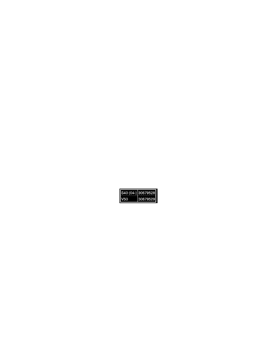
Note! After replacing the subwoofer module (SUB), new software must be ordered and programmed.
Ordering software
Order software. See: See: Testing and Inspection/Programming and Relearning/Software Downloading