
V50 L5-2.4L VIN 39 B5244S7 (2005)
Check
Conditions (unless otherwise specified):
-
Sensor connected.
-
Ignition position II.
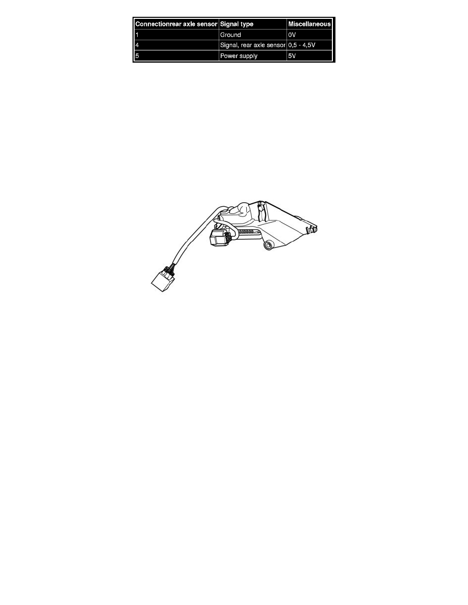
Check 1
Position sensor:
Measure the direct voltage between connections 1 and 4. The value must be: Uapproximately1.5-3.8 V in ignition position II.
GDL-Master and GDL-Slave
General
There are two Gas Discharge Lamp Modules (GDLs), one for each headlamp. The one located on the driver's side of the vehicle acts as "master" and
communicates with the Central electronic module (CEM) via LIN-communication. The other Gas Discharge Lamp Module (GDL)acts as "slave" and
communicates with the "master" control module via LIN-communication.
Other information
An electronic ballast is connected to each headlight. The ballast acts as a voltage regulator and generates alternating voltage (AC).
connection