V50 L5-2.4L VIN 39 B5244S7 (2005)

Trailer Lighting Module: Pinout Values and Diagnostic Parameters
Connecting Breakout Box, Trailer Module (TRM)
Connecting the breakout box
Special tools:
951 1508 Adapter 10-7-5 pin See: Tools and Equipment/951 1508 Adapter 10-7-5 pin
951 2888 16-pin AUD adapter See: Tools and Equipment/951 2888 16-Pin AUD Adapter
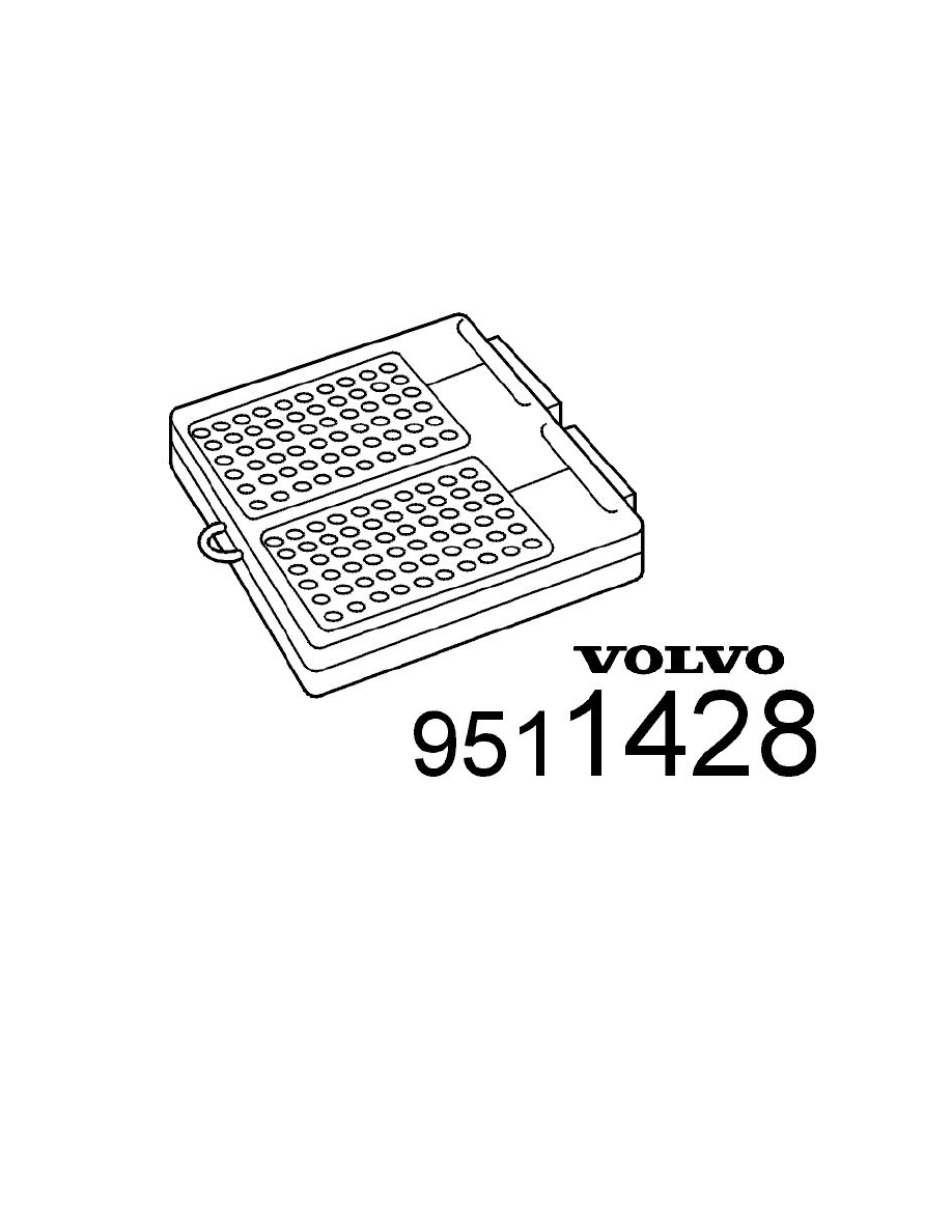
951 1428 Breakout box See: Tools and Equipment/951 1428 Breakout box
Connecting the breakout box
-
Ignition off, wait for at least 1 minute
-
Break the power supply to the trailer module (TRM) by disconnecting the battery negative lead
-
Expose the trailer module (TRM)
-
Disconnect the control module connectors
-
Connect an adapter to connector B (cable harness side). To carry out this procedure, use: 951 1508 Adapter 10-7-5 pin See: Tools and
Equipment/951 1508 Adapter 10-7-5 pin
-
Connect an adapter to connector C (cable harness side). To carry out this procedure, use: 951 2888 16-pin AUD adapter See: Tools and
Equipment/951 2888 16-Pin AUD Adapter
-
Connect a breakout box to the adapter. To carry out this procedure, use: 951 1428 Breakout box See: Tools and Equipment/951 1428 Breakout
box.
The breakout box is designed to facilitate reading off the input and output signals of the control module, when the control module is disconnected. The
use of a breakout box reduces the risk of accidental short-circuited cables and damage to the connector pins.
Disconnecting breakout box
Disconnect the breakout box in reverse order.
Note! It is important to connect the breakout box and check the ground terminals before taking readings.The removed fuses must be reinstalled
before the trailer module (TRM) can be checked and readings taken.
Other information
