
V50 L5-2.4L VIN 39 B5244S7 (2005)
Electronic Throttle Control Module: Description and Operation
Throttle Control
Throttle Control
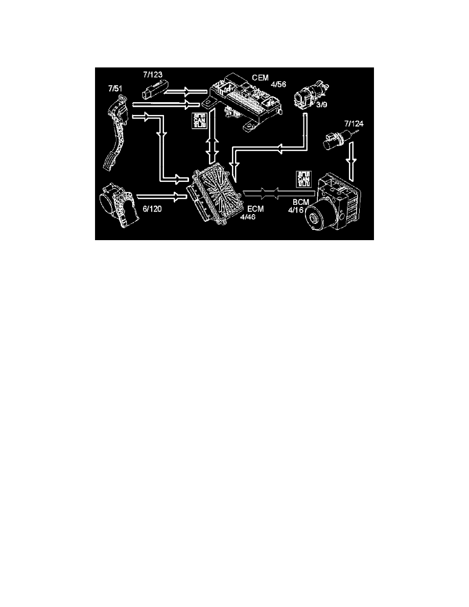
To ensure that the correct throttle angle is reached, the engine control module (ECM) controls the throttle shutter in the throttle unit (6/120), mainly
using the signal from:
-
accelerator pedal (AP) position sensor (7/51)
-
clutch pedal sensor (7/123) via central electronic module (CEM) (4/56)
-
stop lamp switch (3/9)
-
the throttle position (TP) sensor on the electronic throttle unit (6/120)
-
brake pedal sensor (7/124) via brake control module (BCM) (4/16).
Additional signals and parameters are used to ensure optimum throttle control. By example by compensating for:
-
the load from the air conditioning (A/C) compressor
-
the load from the transmission depending on the selected gear mode (automatic)
-
engine coolant temperature (ECT).
In a combustion engine, the difference between the minimum and maximum airflow is considerable. The smaller air flows need more thorough regulation
(for example during idle air trim), so the throttle position (TP) sensor signal 1 is amplified approximately 4 times in the engine control module (ECM)
before it reaches the Analog/Digital converter in the engine control module (ECM). This means that there are three, two real and one fictitious, input
signals available to the engine control module (ECM). These signals are used to determine the position of the throttle disc and to control the throttle
motor to the correct throttle angle.
Because the signal is amplified, it reaches its maximum value at approximately a quarter of maximum deployment.
The engine control module (ECM) primarily uses the signal from throttle position (TP) sensor 1 as a measurement of throttle opening. The signal from
throttle position (TP) sensor 2 is mainly to check that throttle position (TP) sensor 1 is working. The engine control module (ECM) then uses the signal
to calculate a throttle angle (actual value). This is the actual throttle angle. The value for the actual throttle angle is used by those functions in the engine
control module (ECM) which depend on this information so that the throttle can be correctly regulated.
There is an adaptation (learning) in the engine control module (ECM) so that the control module can calculate how the damper motor needs to be
controlled. See "Adaptation of the electronic throttle unit" below. This adaptation occurs automatically when necessary. The engine control module
(ECM) moves the throttle disc to the different positions and reads off and registers the actual values from the throttle position (TP) sensors.
The throttle angle is regulated so that the actual angle (actual value) is the same as the angle calculated by the engine control module (ECM) (desired
value). The engine control module (ECM) also uses the values that were stored during adaptation of the throttle angle, and the actual signals from the
throttle position (TP) sensor.
The damper motor is deployed by the integrated power stage in the engine control module (ECM) using a pulse width modulation (PWM) signal. The
torsion from the opening and return springs in the electronic throttle unit is also used. If the engine control module (ECM) detects a fault in the electronic
throttle unit so that the throttle disc cannot be controlled, the springs in the throttle unit will turn the throttle disc to the limp home position (return
position). This return position is calibrated to provide a throttle angle large enough to allow the car to be driven to a workshop, although with
considerably reduced drivability.