
V50 L5-2.4L VIN 39 B5244S7 (2005)
If the reading is not correct. Replace the cable and/or continue according to "Contact Resistance and Oxidation".
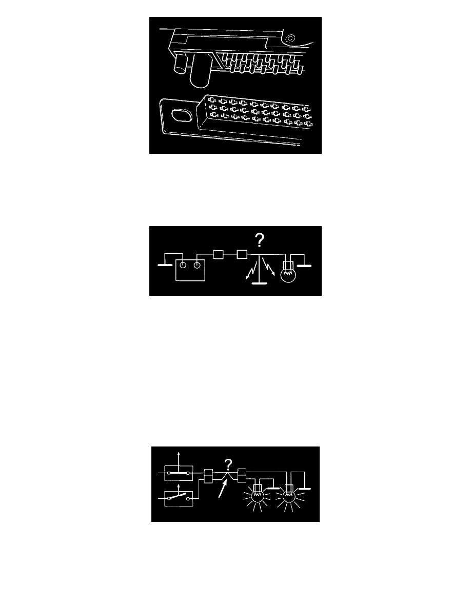
Always check the control module and control module box connectors to ensure that their pins and sockets are not bent or damaged, this may cause faults.
Check pins and terminals particularly carefully.
Short-Circuit to Ground, Intermittent Faults
Short-circuit to ground, intermittent faults
A short-circuit between a live cable and ground is often indicated by the loss of a function or a fuse blowing when a current is passed through the cable.
Repair wiring and cable terminals as required, using appropriate procedures.
Checks:
-
Check the cables visually according to "Inspect Terminals Visually". Activate all switches and sensors in the circuit. Check whether the fuse
blows.
-
Disconnect the connectors in the circuit to ensure that they do not affect readings.
Connect an ohmmeter between cable and ground. The ohmmeter should read infinite resistance if no components are connected.
Shake the cable lightly and pull on connectors during measurement to locate the damage.
If the value is not correct, try a new cable and/or continue according to "Contact Resistance and Oxidation".
Short-Circuit to Supply Voltage. Intermittent Faults
Short-circuit to supply voltage, intermittent faults
A short-circuit between a cable and supply voltage is often indicated by the loss of a function or a fuse blowing when a current is passed through the
cable.
Repair wiring and cable terminals, using appropriate procedures.
Checks: