
V50 T5 AWD L5-2.5L Turbo VIN 67 B5254T7 (2008)
A = Frame
B = Header
C = Message
A message on LIN is called a frame and consist of the following parts:
1. Synchronization interrupt.Used to wake slave nodes that are in sleep mode.
2. Synchronization field. The synchronization field helps slave nodes to synchronize with their master node's clock frequency, in order for messages
sent to be received correctly.
3. Identification field. Contains information about the contents of the message. All nodes can read and respond to a message, yet only one node has
the right to send a response to the message. Which node has the right to answer the message (send response data) is evident from the identifier.
4. Data information. The data sent can be two to eight bytes long. The data information is sent with the least significant bit first.
5. Checksum. The checksum is a way for slave notes to check whether the received message has been transferred correctly, or if any disturbance can
have occurred during the transmission which has corrupted the data. If an error has occurred in a message during transmission from the master
node to the slave node, i.e. the checksum calculated by the slave node does not correspond, the slave node will erase the message and await the
next message sent from the master node.
The slave nodes do not send an acknowledgement to a message that has been received correctly. The master node re-reads the message sent out on the
LIN bus and compares the re-read message with the message that was sent.
If the sent and detected messages are the same, the master mode presupposes that the message has been received correctly by the slave nodes.
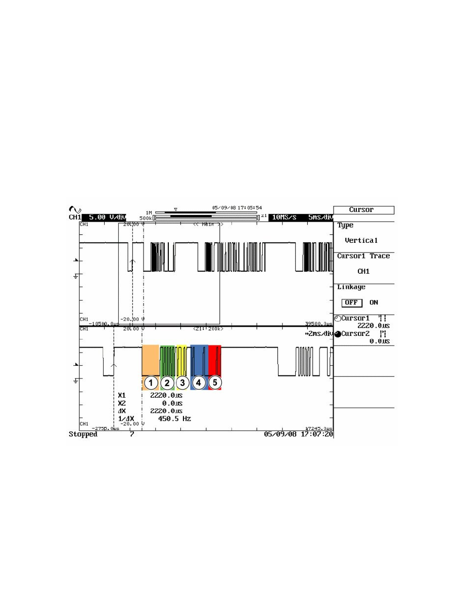
Example from an oscilloscope
If you have access to an oscilloscope and measure on the LIN bus, a start-up procedure with subsequent communication can appear as illustrated in the
figure above.
The lower curve is a magnified section of the upper curve.
In the upper curve you first see the LIN bus in sleep mode with the subsequent message. This is followed by several messages.
The numbers in the different fields correspond to the parts of the message described in the list above.
In the figure you can see, among others, that the sleep voltage on the LIN bus is approximately 13 V and that the voltage drops to approximately 1 V
during communication.
Note! The figure above is only one example of how messages on the LIN network can appear.
Error Management In the Local Interconnect Network (LIN)
Error management in the Local Interconnect Network (LIN)