
V50 T5 AWD L5-2.5L Turbo VIN 67 B5254T7 (2008)
grounded (control) in the engine control module (ECM).
When leak diagnostics are not active, the valve is held open to ambient air for EVAP control to be carried out.
During leak diagnostics the pump in the leak diagnostic unit starts. The valve in the unit is operated by the engine control module (ECM) by grounding
the different circuits internally in the engine control module (ECM).
The Engine control module (ECM) checks the fuel tanks system for leaks by pressurizing the system and at the same time monitoring a number of
relevant parameters. Also see: Leak diagnostics (certain markets only) See: Computers and Control Systems/Description and Operation/Leak
Diagnostics (Certain Markets Only)
The engine control module (ECM) can diagnose the leak diagnostic unit.
The valve in the leak diagnostic unit can be activated.
The leak diagnostic unit is at the upper front edge of the fuel tank.
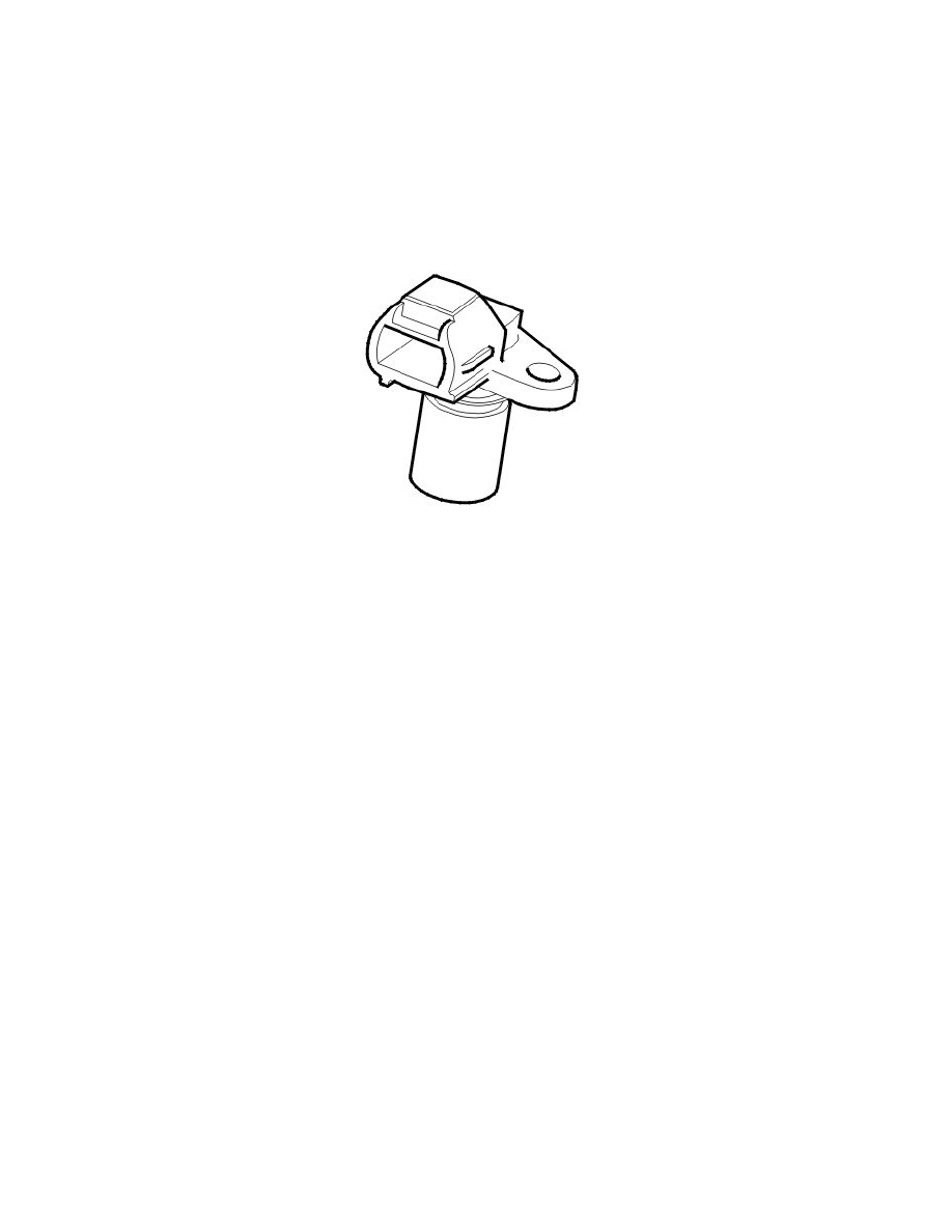
Engine speed (RPM) sensor
The engine speed (RPM) sensor provides the Engine Control Module (ECM) with information about the speed and position of the crankshaft. The
engine control module (ECM) is able to use the signal from the engine speed (RPM) sensor to determine when the piston in cylinder 1 is approaching top
dead center (TDC). However it is unable to use the signal from the engine speed (RPM) sensor to determine whether the piston is in the combustion
stroke or whether the exhaust valve is open (exhaust stroke). The signal from the camshaft position (CMP) sensor is also required to determine the
operating cycle of the engine.
The signal from the engine speed (RPM) sensor is also used to check the engine for misfires. For more information, see: Misfire diagnostic See:
Computers and Control Systems/Description and Operation/Misfire Diagnostics
There is a steel ring with stamped holes welded to the rim of the primary section (the section fixed to the crankshaft) of the flywheel.
The holes are positioned with a gap of 6° between each hole. This arrangement creates a hole for each tooth. There are 360° in one revolution. 6°
between each hole means that there are 60 holes. However two holes are not stamped, to create a reference position (long gap - missing tooth) for the
crankshaft. The first tooth after the reference position is located 84° before TDC on cylinder 1. See: Function See: Computers and Control
Systems/Description and Operation/Engine Control Module (ECM)/Function
The engine speed (RPM) sensor is at the rear of the engine above the flywheel.
The sensor is inductive with a permanent magnet. An alternating current is induced in the sensor when the flywheel/carrier plate passes the engine speed
(RPM) sensor. The generated voltage and frequency increases with the engine speed (rpm).
The signal varies between 0.1-100 V depending on the engine speed (RPM).
The Engine Control Module (ECM) is able to determine the engine speed (RPM) by counting the number of holes per time unit. When the reference
position passes the engine speed (RPM) sensor, the voltage and frequency drop momentarily to zero, even though the engine is still running. This allows
the engine control module (ECM) to determine the position of the crankshaft.
If the signal from the engine speed (RPM) sensor is incorrect or missing, the control module will use the signals from the camshaft position (CMP)
sensor, on the condition that the position of the camshaft has been adapted. This means that the car can be driven if the signal is missing.
The engine control module (ECM) can diagnose the engine speed (RPM) sensor. The sensor value (engine speed (rpm)) can be read off using VIDA.
Part 2
Design (Continued)
Fuel pressure sensor / fuel temperature sensor