
V50 T5 AWD L5-2.5L Turbo VIN 67 B5254T7 (2008)
The function of the accelerator pedal (AP) position sensor is to provide the engine control module (ECM) and central electronic module (CEM) with
information about the position of the accelerator pedal. This data is used by the engine control module (ECM) to deploy the shutter in the throttle unit to
the correct angle.
The sensor consists of a plastic housing with two potentiometers, an AC/DC converter and circuits. The potentiometers are connected to a shaft which is
affected by the position of the accelerator pedal (AP). The resistance in the potentiometers changes with the position of the accelerator pedal (AP).
The accelerator pedal (AP) position sensor transmits an analog and a digital signal (pulse width modulated (PWM) signal). The signals give information
about the position of the accelerator pedal (AP). The digital signal is generated by the AC/DC converter in the sensor and is transmitted to the engine
control module (ECM). The analog signal is transmitted central electronic module (CEM) and on to the engine control module (ECM) via the controller
area network (CAN). The analog and digital signals are used at the same time by the engine control module (ECM) to regulate the throttle shutter angle.
The sensor is supplied with 12 V by the system relay via a fuse and is grounded in the car body.
The digital signal is also used in conjunction with the analog signal for accelerator pedal (AP) position sensor diagnostics. The accelerator pedal (AP)
position sensor signals can be read off using VIDA. A diagnostic trouble code (DTC) is stored if the engine control module (ECM) detects a difference
between the analog and digital signals. The engine control module (ECM) then uses a minimal value to ensure the function (limp home).
The accelerator pedal (AP) position sensor is located on the accelerator pedal bracket.
Clutch pedal switch
Engine control module (ECM) receives information about the clutch pedal's position in two ways.
Partly from a clutch pedal position sensor which is directly connected to Central electronic module (CEM), and partly from a clutch pedal switch directly
connected to the Engine control module (ECM).
The function of the clutch pedal switch is to provide extra safety for the function autostart. In order for the function to be activated, the Engine control
module (ECM) must receive signal that indicates pressed down pedal from the clutch pedal switch.
To start without the function autostart it is enough that any of the signals (from clutch pedal position sensor or clutch pedal switch) indicates pressed
down pedal.
For more information about the clutch pedal position sensor, see Design and Function, central electronic module (CEM).
In its starting position, the clutch pedal switch is open (clutch pedal released). The switch's installation shall be adjusted so that is is closed when the
clutch pedal passes 75% of full pedal movement.
The clutch pedal switch is on the pedal box by the clutch pedal.
The engine control module (ECM) can diagnose the clutch pedal switch. The status (position) of the switch can be read using the diagnostic tool.
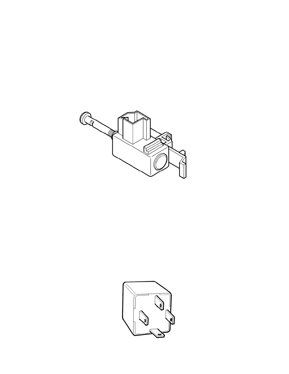
Main relay (system relay)
The function of the main relay (system relay) is to supply certain components with voltage.