
V50 T5 AWD L5-2.5L Turbo VIN 67 B5254T7 (2008)
Headlamp Control Module: Description and Operation
System Overview
System overview
Control module
The primary task of the headlamp control module (HCM) is to manage the functions of:
-
Automatic headlamp levelling (vehicles with Bi-Xenon lamps)
-
Active headlamps (vehicles with active headlamps only)
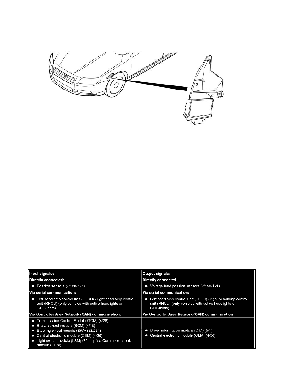
The control module is installed on a a console on the left fender liner. When replacing, remove the whole control module from the vehicle.
Headlamp Control Module (HCM) communicates both with directly connected components, and with other control modules via CAN-communication
and LIN-communication.
The control module checks its calculations all performed activations as well as input and output signals with integrated diagnosis. When the control
module detects a problem, a diagnostic trouble code is generated.
Any diagnostic trouble codes are stored in the relevant control module memory. The data can be read off using a diagnostic tool.
If the control module detects a problem, a diagnostic trouble code is registered in the control module's internal memory. At the same time, a number of
frozen values stored from the time when the problem occurred.
Depending on how serious the problem is, certain functions will be completely or partly disconnected. A warnings or information text will be shown in
the text display in the Driver information module (DIM).
If the vehicle is equipped with active headlights and these are activated (light switch in position "3"), the diode in Light switch module (LSM) will flash.
Diagnostic trouble codes (DTCs) and frozen values (extended fault code information) can be read off using the diagnostic tool via the data link
connector (DLC) in the vehicle.
Ignition switch position II must be activated to check that the headlamp control module (HCM) is supplied power and is grounded. If the headlights
make a reference sweep, the headlamp control module (HCM) is receiving power.
For further information, also see Signal specifications.
Signals
The table below summarizes the input signals to and output signals from the headlamp control module (HCM). The signal types are divided into directly
connected signals, serial communication and CAN communication. The illustration below displays the same information with the Volvo component
designations.