
V50 T5 AWD L5-2.5L Turbo VIN 67 B5254T7 (2008)
Overview
The boost pressure sensor is a combined sensor and contains two sensors in the same component:
-
manifold absolute pressure (MAP) sensor
-
temperature sensor.
The boost pressure sensor is on the right-hand upper section of the charge air cooler (CAC).
Manifold absolute pressure (MAP) sensor
The manifold absolute pressure (MAP) sensor detects the pressure in the intake manifold downstream of the charge air cooler (CAC). The signal from
the sensor is primarily used by the engine control module (ECM) to check that the correct boost pressure is reached. The boost pressure is governed by
the turbocharger (TC) control valve.
The sensor, which is a piezo resistor, is grounded in the control module and supplied with 5 V from the control module.
The resistance in the sensor changes depending on the pressure in the intake manifold, giving a signal of 0.5-4.5 V. Low pressure results in low voltage,
high pressure on high voltage.
The engine control module (ECM) can diagnose the manifold absolute pressure (MAP) sensor. The sensor signal can be read using VIDA.
Temperature sensor
The temperature sensor detects the temperature of the intake air after the charge air cooler (CAC). This data is used by the engine control module (ECM)
to calculate the boost pressure control and to calculate the injection period. The control module also controls certain diagnostic functions using the signal
from the temperature sensor.
The sensor, which is an NTC resistor, is grounded in the control module and supplied with power (signal) from the control module.
The resistance in the sensor changes according to the temperature of the intake air. This provides the control module with a signal of between 0.5-5 V.
The lower the temperature the higher the voltage (high resistance). A high temperature results in low voltage (low resistance).
The engine control module (ECM) can diagnose the temperature sensor. The sensor signal can be read using VIDA.
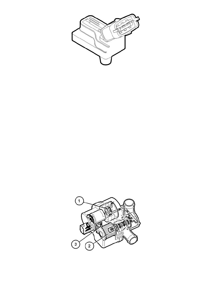
Leak diagnostic unit (certain markets only)
The function of the leak diagnostic unit is to pressurize the fuel tank system during leak diagnostics.
The leak diagnostic unit consists of a plastic housing with:
1. electrical air pump
2. a valve / solenoid which governs the air flow in the unit
3. a heater element (PTC resistor) which warms up the pump.
The electrical pump, valve and heater element in the unit are supplied with voltage by the system relay. The pump, valve and heater element are