
V70 2.4 L5-2.4L VIN 61 B5244S (2001)
Installing the control module
-
Press the control module into place so that the catch on the rear engages
-
Position the connector. Carefully press the connector down.
Note! The pins are fragile. Check that the connector goes straight down into the control module.
-
Tighten the screw for the connector
-
Check that the connector cover is correctly positioned. Remedy if necessary.
-
Install relays and shunts.
-
Install the relay box.
-
Install the soundproofing panel on the driver's side.
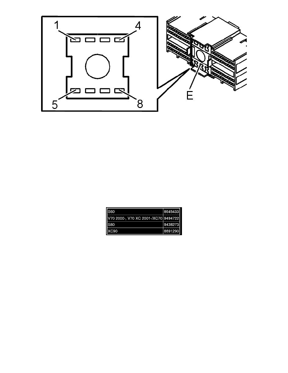
Ordering and programming software
Order and program software following the table below.
Finishing
-
Program in the data read off from the old control module (customer-programmed data for example). This is performed via VIDA vehicle
communication.
-
Reset the service reminder indicator (SRI). Otherwise the lamp will receive incorrect reference data. (Global time is reset when the central
electronic module (CEM) is replaced.) Reset the service reminder indicator (SRI) according to Resetting the service reminder indicator (SRI) See:
Instrument Panel, Gauges and Warning Indicators/Maintenance Required Lamp/Indicator/Service and Repair
-
Check that the control area network (CAN) is functioning. This is done by reading off the control module ID for the central electronic module
(CEM), rear electronic module (REM) and engine control module (ECM) via VIDA vehicle communication.
Other information
For the location of other relay and fuse boxes, see Relays, fuse boxes and wiring See: Power and Ground Distribution/Locations