
V70 2.4 L5-2.4L VIN 61 B5244S (2001)
Transmission input speed sensor (speed of the input shaft)
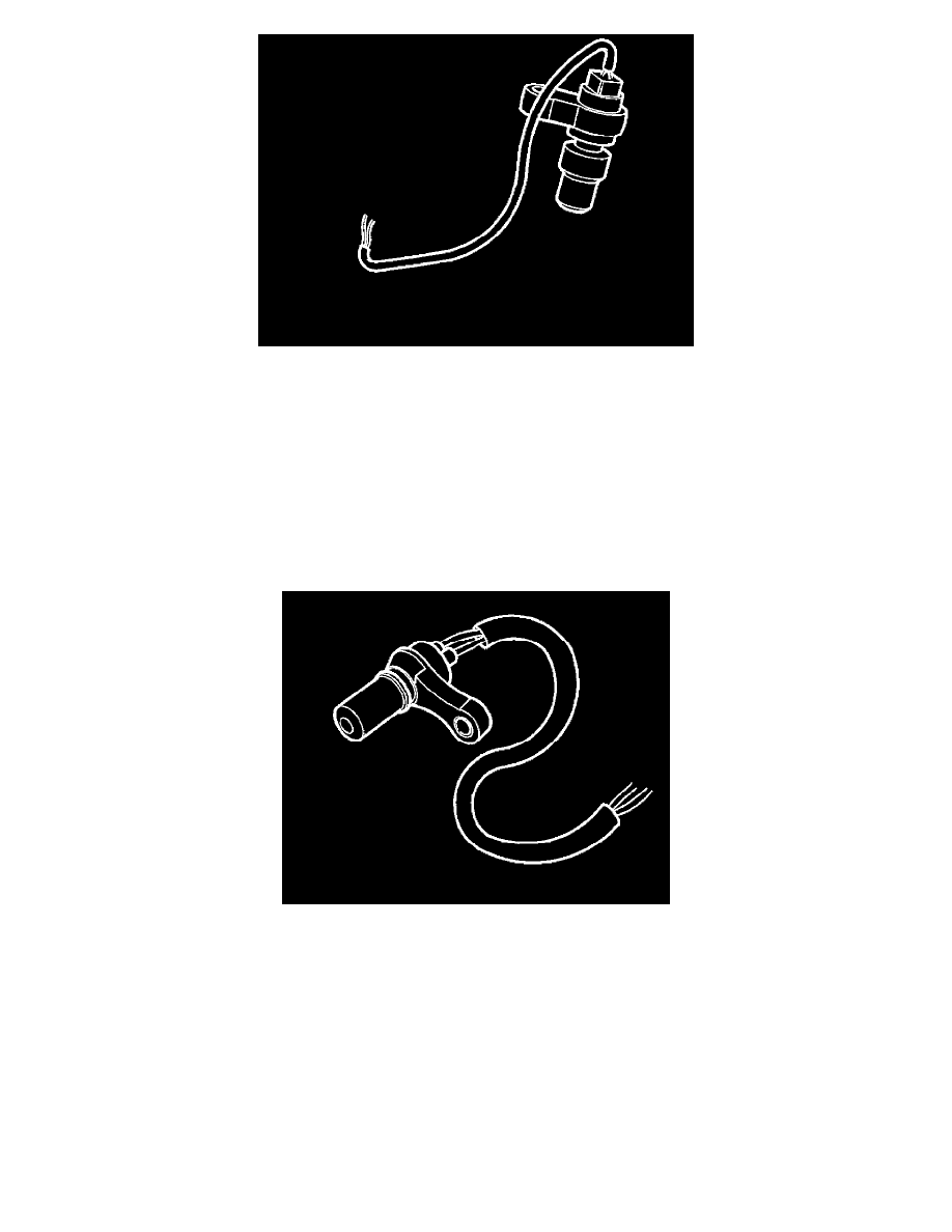
The transmission input speed sensor (speed of the input shaft) is on the top of the transmission housing. The sensor is an active sensor and is supplied
with 12 V. When the pulse wheel on clutch C1 rotates, the sensor generates a pulsed current (quadratic wave) where the strength of the current
depends on the position of the pulse wheel. The signals from the coils in the sensor are then affected by a magnetic resistance element, which
generates a current which oscillates between 7 mA and 14 mA, and whose frequency increases with speed. Using the signal from the sensor, the
transmission control module (TCM) calculates the transmission speed, unit rpm.
The transmission control module (TCM) uses information about the input shaft speed to calculate the torque reduction to be requested from the engine
control module (ECM) when shifting. The value is also used to compare the engine speed (RPM) with the speed of the input shaft in order to
calculate the slipping rate of the torque converter. The value is also compared with the transmission speed sensor signal in order to calculate the actual
gear ratio. This is done to check whether the value corresponds to the expected gear ratio.
There are diagnostics for the transmission in out speed sensor
Transmission output speed sensor (speed of the output shaft)
The transmission output speed sensor (speed of the output shaft) is on the reverse of the transmission housing. The sensor provides signals to the
transmission control module (TCM) about the vehicle speed. The output shaft speed sensor is an active sensor and is supplied with 12 V. When the
pulse wheel (wheel for shift-lock) rotates the sensor generates a pulsed current (quadratic wave) where the strength of the current depends on the
position of the pulse wheel. The signals from the coils in the sensor are then affected by a magnetic resistance element, which generates a current
which oscillates between 7 mA and 14 mA, and whose frequency increases with speed. The control module calculates the transmission output speed
using the signals from the sensor. The signal is compared with the signal from the transmission input speed sensor and is used to calculate the gear
ratio and is also used for diagnostics.
There are diagnostics for the transmission output speed sensor.