
V70 2.4T L5-2.4L Turbo VIN 58 B5244T3 (2002)
Housing Assembly HVAC: Description and Operation
General
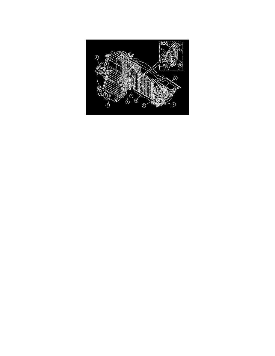
Design, Climate Control Unit
The climate control unit consists of the following components:
1. Heater element.
2. Damper motor, temperature, left.
3. Blower fan.
4. Damper motor, fresh air / recirculation.
5. Power unit for blower fan motor.
6. Particle filter.
7. Damper motor, ventilation and floor (also defroster for MCC/STD).
8. Damper motor, temperature, right.
9. Damper motor defroster (ECC).
Engine coolant constantly flows through the heater element. There is no valve to regulate the flow. The selected temperature is achieved using dampers
for the right and left-hand sides of the car installed upstream and downstream of the heater element. These control the amount of air to be warmed. There
are also dampers downstream of the heater element that guide the airflow to the correct air vent.
The climate control module provides infinitely variable electronic blower fan control. When AUTO mode (only electronic climate control) is engaged
the climate control module (CCM) adapts the blower fan speed to the setting of the controls and the vehicle speed. The blower fan can be set to run-on in
order to reduce residual moisture in the evaporator.
A timer located in the central electronic module (CEM) controls the run-on time. 50 minutes after the engine has been switched off and the ignition has
been turned to position 0 or 1 the central electronic module (CEM) supplies power to the climate control module (CCM) and the blower fan is activated
at full speed for 7 minutes. This run-on dries the evaporator and prevents bad odors.
This function is programmed at the factory, but can be deactivated in the event of customer complaints via programming of customer parameters.
Programming is carried out via VADIS.
The function is only available to cars of structure week 199850 and later.
All damper motors are of the stepper type. Their position and speed is controlled electronically.
Manual climate control and standard climate control have four stepper motors controlling the following dampers:
-
Ventilation / floor / defroster via a link system.
-
Recirculation and fresh air via a link system.
-
Temperature left.
-
Temperature right.
For electronic climate control (ECC) there is an extra stepper motor which controls the defroster. The wiring between the damper motors and the climate
control module (CCM) consists of four cables for supply voltage and directional control and a separate cable for each motor which controls the motor to
be activated. Each motor has four coils. The corresponding coils in each motor are supplied with power at the same time. The motors are only supplied
with power if they are grounded at the same time. When a new position is selected for the damper motor, the climate control module (CCM) calculates
how many steps are required to complete the movement. The climate control module (CCM) then activates the damper motor with the necessary number
of steps. When the motor is instructed to move an end position, the motor is activated until it stops. This end position is then used as a limit position.
This means that the damper motors are self-adjusting, but only after the limit positions have been reached. When replacing the damper motors, ensure
that the self adjustment is carried out. Otherwise the customer may experience defective climate control.