
V70 2.5T AWD L5-2.5L Turbo VIN 59 B5254T2 (2003)
When the correct valve clearance is reached
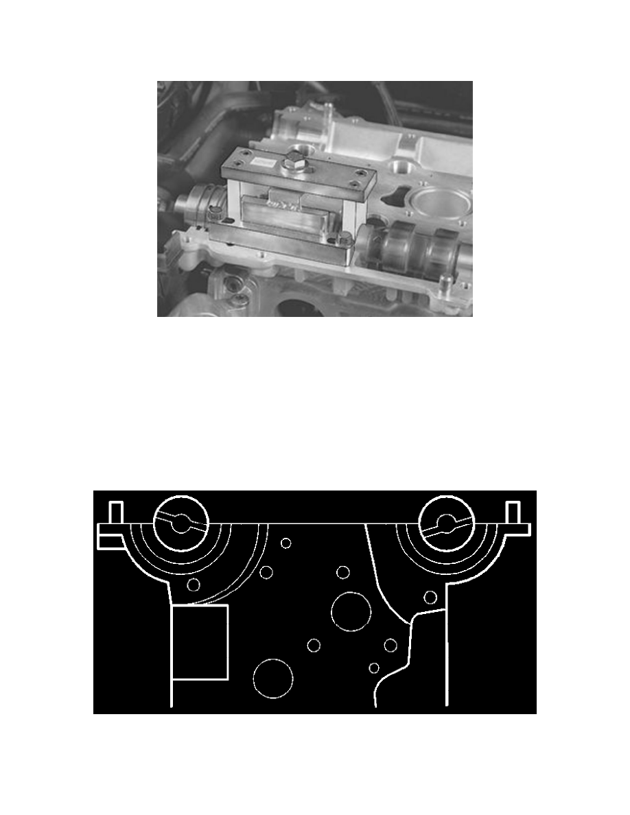
Remove
-
the press tool 999 5765
-
the camshaft
-
the valve lifters.
NOTE: Carefully mark the valve lifters so that exact reinstallation can be carried out.
Example:
Intake side: I1, I2, I3..........................................................................................................................................................................................................I10.
Exhaust side: A1, A2, A3.................................................................................................................................................................................................A10.
Repeat the procedure for measuring the valve clearance for all cylinders on both the intake and exhaust sides.
Installing valve lifters and camshafts
-
Lubricate the valve guide wells.
-
Install all the valve lifters.
-
Lubricate the camshaft bearing seats and the upper sides of the valve lifters.
-
Position the intake camshaft. Ensure that the groove at the rear edge of the camshaft is above an imaginary center line.
-
Position the exhaust camshaft. Ensure that the groove at the rear edge of the camshaft is below an imaginary center line.