
V70 2.5T AWD L5-2.5L Turbo VIN 59 B5254T2 (2003)
Electronic Throttle Actuator: Description and Operation
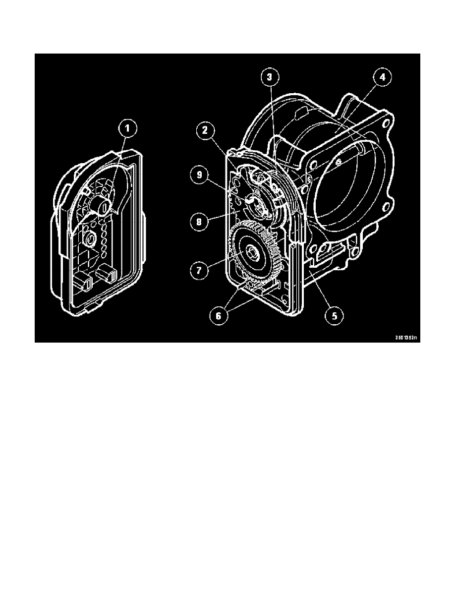
ETA (Electronic Throttle Actuator)
1. Hall sensor
2. Spring
3. Spring
4. Throttle
5. DC motor
6. Terminal pins
7. Gear wheel
8. Gear sector
9. Permanent magnets.
Function
The engine control module (ECM) uses a PWM signal to control the position of the DC motor and with it the position of the throttle.
By changing the polarity of the power supply, the DC motor can be run in both directions.
Two permanent magnets in the gear sector on the throttle spindle are used to check the position of the throttle.
-
The permanent magnets affect the two Hall sensors in the cover
-
When the throttle spindle is turned, the position and strength of the magnetic field changes, which affects the Hall sensors
-
Internal circuits convert the hall signals to two voltage signals which are transmitted to the engine control module (ECM).
The two signals are offset internally.
-
The voltage of the main signal is 0.6 V when the throttle is shut. The voltage increases by 40 mV per degree that the throttle is opened. The
voltage is nearly 4 V at wide open throttle (WOT)
-
The voltage of the redundant signal is 1.48 V when the throttle is shut. The voltage increases by 32 mV per degree that the throttle is opened. The
voltage is nearly 4.2 V at wide open throttle (WOT).