
V70 2.5T AWD L5-2.5L Turbo VIN 59 B5254T2 (2003)
-
the plastic nuts from the cover in the fender liner
-
the right front wheel.
Install (turbocharged engine)
-
a new cover over the intake camshaft
-
secure the cable harness for the injector
-
charge air pipe above the engine and holder at the rear of the engine.
Install (common)
-
the plastic nuts from the cover in the fender liner
-
the right front wheel.
Valve clearance, setting/adjusting
Special Tools: 951 2767, 999 5450, 999 5451, 999 5452, 999 5454, 999 5670, 999 5718, 999 5719, 999 5752, 999 5765
NOTE: There are a number of versions of the variable valve timing unit. Therefore it is extremely important to always read the information referring to
the engine variant/model year to be remedied.
Preparation
-
Remove the cable from the battery negative terminal.
-
Check the valve clearance.
NOTE: Make a note of the valve clearance in the inspection form.
Remove
-
the cross stay between the suspension turrets
-
the ground strip from the cylinder head
-
the upper engine stabilizer brace
-
the cover in the cylinder head at the rear of the exhaust camshaft
-
the crankcase ventilation hose from the top of the camshaft cover
-
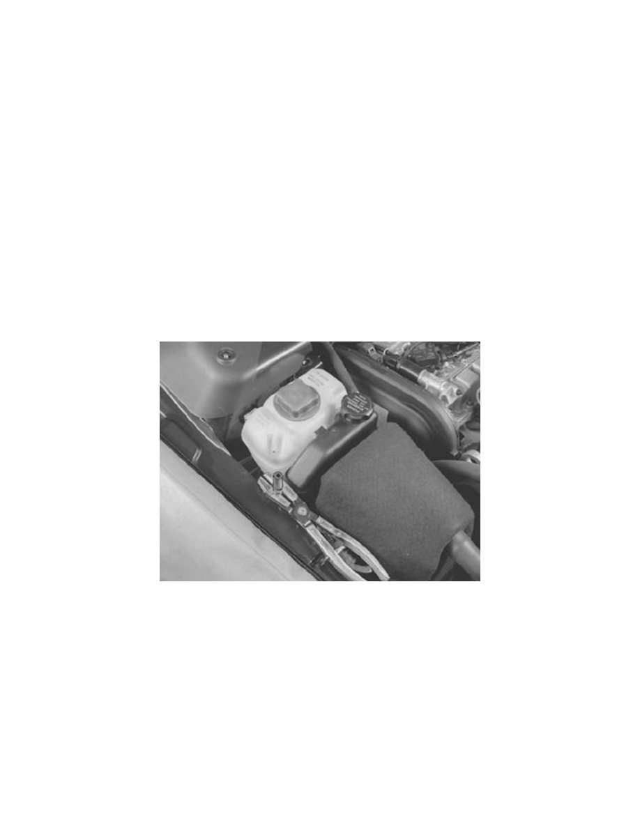
the radiator breather tube from the expansion tank. Install lock grip pliers.
Lift up the brake fluid reservoir.
Disconnect the ABS sensor connector.
Place the brake fluid reservoir over the engine.
WARNING: Ensure that no fluid is spilled on the engine. It is extremely flammable.
Disconnect the connector for the level sensor in the expansion tank.