
V70 GL L5-2.4L VIN 55 B5254S (1998)
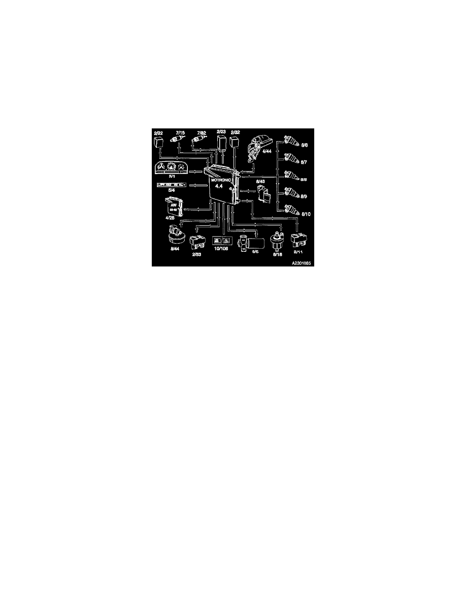
^ Ignition, by transmitting signals to the Ignition Discharge Module (IDM) integrated with the Ignition Coil (4/44)
^ Idling speed, by operating the Idle Air Control (IAC) Valve (8/5)
^ Pressure in the inlet manifold during engine braking by regulating the Idle Air Control (IAC) Valve (8/5)
^ Engine cooling fan, by activating the Fan Control (FC) Relay (2/11)
^ EVAP System Canister Purge (CP) Valve (8/18)
^ Malfunction Indicator Lamp (MIL) (10/106) for exhaust emission related faults
^ Heating of front and rear Heated Oxygen Sensors (HO2S) (7/15 and 7/82)
^ A/C Compressor Relay (2/22), to switch off the compressor.
^ EVAP Canister Shut-Off Valve (8/44)
^ Pulsed Secondary Air Injection System (PAIR) Pump, by activating the Pulsed Secondary Air Injection System (PAIR) Pump Relay (2/53).
OTHER OUTPUT SIGNALS
The Engine Control Module also transmits signals to the following components:
^ Acknowledgment of torque limiting through timing retardation, to the Automatic Transmission Control Module (TCM) (4/28)
^ Engine speed and load signals to the Automatic Transmission Control Module (TCM) (4/28)
^ Throttle angle signal to the Automatic Transmission Control Module (TCM) (4/28)
^ Engine Speed (RPM) Signal to the Combined Instrument Panel Tachometer (5/1)
^ Engine Coolant Temperature (ECT) Signal to the Combined Instrument Panel (5/1)
^ Injected fuel quantity to the Combined Instrument Trip Computer (5/4)