
V70 GL L5-2.4L VIN 55 B5254S (1998)
Knock Sensor: Description and Operation
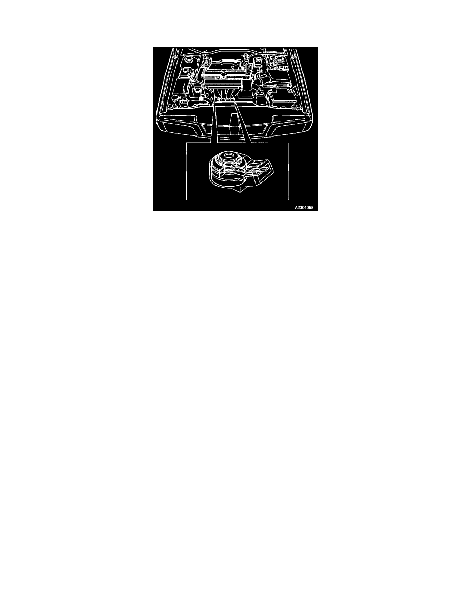
KNOCK SENSORS
The function of the two Knock Sensors (KS) is to provide the Engine Control Module (ECM) with signals to determine whether the engine is
knocking.
The engine control module (ECM) uses the knock sensor (KS) and Camshaft Position (CMP) Sensor signals to identify the cylinder in which knock is
present.
The engine management system incorporates two knock sensor (KS), each of which consists of the following components:
^ Housing:
^ Sleeve
^ Piezoelectric crystal
^ Contact strips
^ Damping weight
^ Washer
^ Nut
Engine knock produces vibrations which are transmitted through the block. The piezoelectric crystal reacts to these by transmitting a signal, which is a
function of the frequency and amplitude of the sound waves, to the engine control module (ECM).
The front knock sensor (KS) detects knock in cylinders 1, 2 and 3, while the rear knock sensor (KS) serves cylinders 4 and 5.
The knock sensors (KS) are mounted on the cylinder block.