
V70 GL L5-2.4L VIN 55 B5254S (1998)
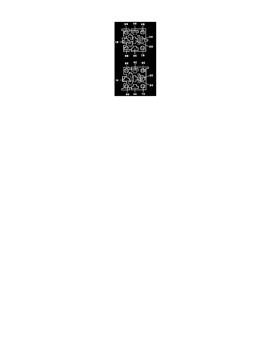
Cruise Control Module: Connector Views
1B
Power supply
Control module power supply.
3B
Ground
Control module ground connection
4B
Diagnostics
Binary signals that can be both input and output
6B
Stop (Brake) light
Battery power when brake pedal is depressed. When brake pedal is up the connection should be grounded via the stop light bulbs. The connection
can also have supply voltage when the ignition is in the OFF position.
7B
Vacuum pump
Activated when system is being controlled and speed is to be increased. Non-continuous ground with the frequency controlled by the control
module.
8B
Speed signal
Signal originates at the speedometer in the form of a sine wave. Transformed in the speedometer to a square wave with a frequency proportional to
the speed.
9B
Regulator
Activated constantly when the system is active and the speed is to be increased or held constant. When speed is to be reduced there is a
non-continuous ground signal with a frequency regulated by the control module.
3E
Park/Neutral position switch
Body ground through starter when gear selector is in the N or P position in a car equipped with automatic transmission. Battery power during
starting.
4E
SET+
Battery power when switch is in the SET+ position.
6E
RESUME
Battery power when selector switch is in RESUME position.
7E
Power supply to vacuum pump and regulator
A relay in the control module feeds battery power to the vacuum pump and regulator. The relay is operated when the system is operational, that is
to say all input signals and internal safety functions have the value and status for approval by the control module.
8E
SET-
Battery power when switch is in the SET- position.
9E
Brake and clutch valve
Battery power when selector switch is set to ON or RESUME and brake and clutch pedals are up.