
V70 XC AWD L5-2.4L Turbo VIN 56 B5254T (1998)
Engine Control Module: Description and Operation
SYSTEM OVERVIEW
The Motronic 4.4 is an Electronic Fuel / Ignition Engine Management System which controls:
^ Fuel Injection
^ Ignition
^ Engine Idle Speed
^ Engine Cooling Fan (FC)
^ Evaporative Emission (EVAP) System
^ A/C System
^ Pulsed Secondary Air Injection System (PAIR)
The Engine Control Module (ECM) incorporates microprocessor which receives signals from the various sensors in the car. The micro-processor uses
a program to compute the necessary engine management functions.
The Engine Control Module incorporates adaptive functions, which enable it to adjust its computations continuously to suit running conditions.
Efficient engine management maintains low exhaust emissions. Since CO content and idling speed do not require adjustment, service requirement is
minimal.
The Engine Control Module also incorporates an On-Board Diagnostic (OBD) function. Signals from sensors, and the operation of the Three-Way
Catalytic Converter (TWC) and EVAP system are continuously monitored. If possible the engine control module (ECM) will adopt fixed substitute
values (limp-home values) to enable the car to be driven if certain signals are faulty or missing.
Substitute values can be adopted for:
- Engine Coolant Temperature (ECT) Sensor
- Throttle Position (TP) Sensor
- Heated Oxygen Sensors (HO2S)
- Mass Air Flow (MAF) Sensor
Faults are recorded in the Engine Control Module memory in the form of Diagnostic Trouble Codes (DTCs). Information can be read-off using the
Volvo Scan Tool (ST) connected to the Data Link Connector (DLC) in front of the gear shift and under the coin tray on the center console.
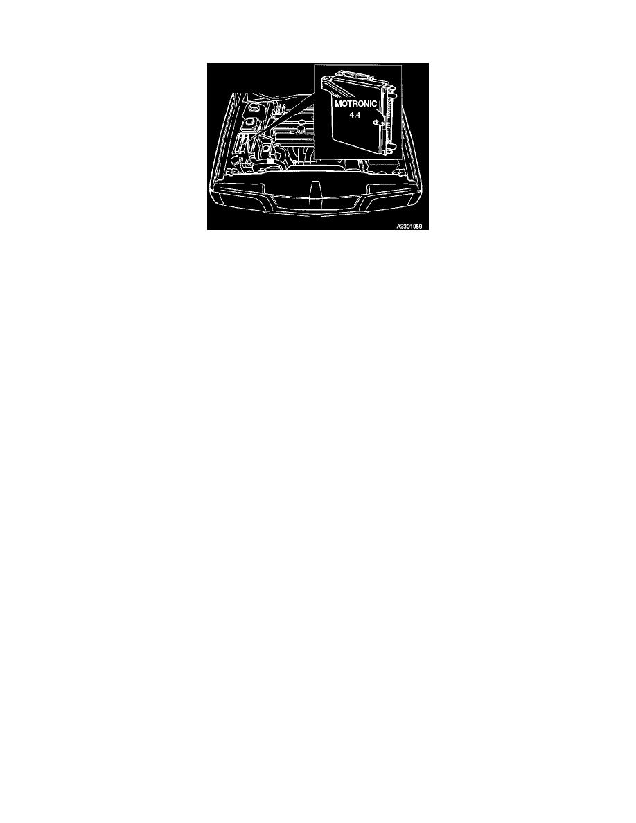
The Engine Control Module is housed in a ventilated box in the engine compartment.
INPUT SIGNALS