
V70 XC AWD L5-2.4L Turbo VIN 56 B5254T (1998)
Engine Speed Sensor: Description and Operation
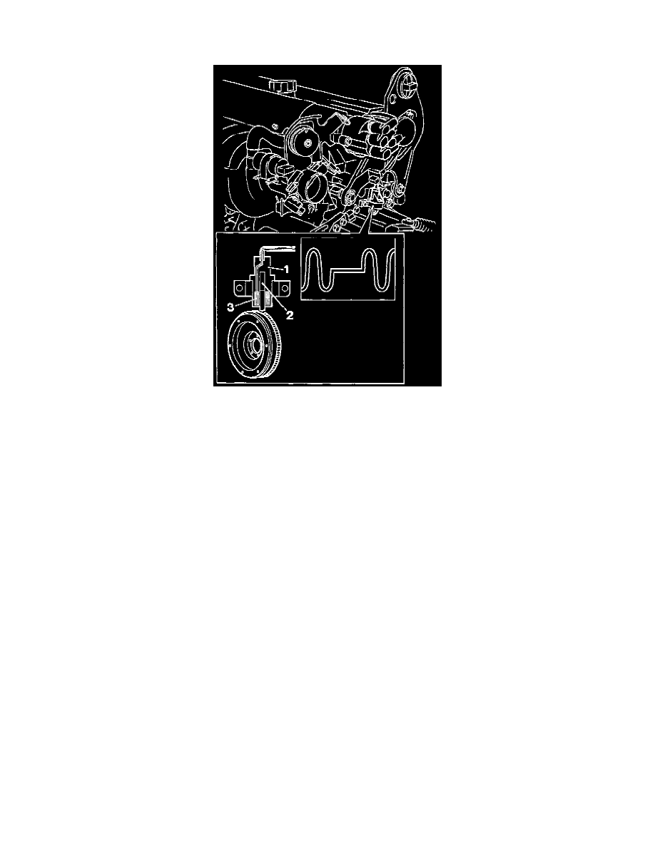
ENGINE SPEED SENSOR
The periphery of the flywheel/carrier plate is provided with a series of holes. As it passes, each hole induces a voltage in the pick-up coil of the Engine
Speed (RPM) Sensor. The passage of several holes generates an A/C signal the frequency of which is a function of the number of holes passing per
second and the voltage of which can vary between 0.1 V and 55 V, depending on the engine speed (RPM) and temperature. Voltage increases with
engine speed (RPM). While frequency also increases with engine speed (RPM). The Engine Control Module (ECM) determines crankshaft speed by
recording voltage pulses.
At 90° TDC for cylinder 1 there is a longer hole. When this longer gap passes the engine speed (RPM) sensor, voltage pulses stop and the engine
control module (ECM) can calculate angular camshaft position.
The engine will stop if the signals from the sensor to the engine control module (ECM) cease.
The Engine Speed Sensor consists of the following components:
^ Housing (1)
^ Permanent magnet (2)
^ Coil (3)