
V70 XC AWD L5-2.4L Turbo VIN 56 B5254T (1998)
CAUTION! Avoid touching the contacts on the SRS control unit. There is a risk of an electrostatic discharge which can cause damage to the
control unit.
Assembly
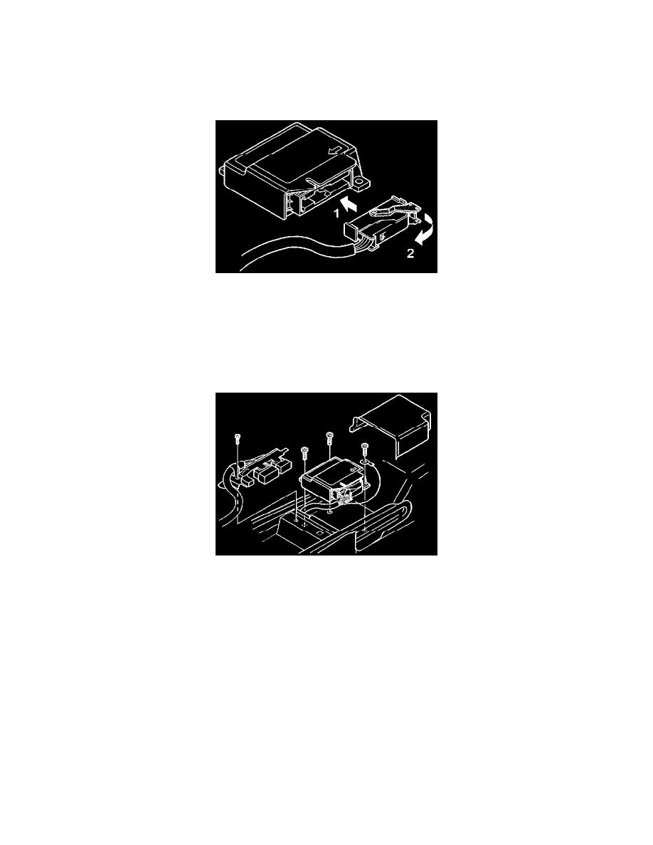
CDC4. Installation of connector to SRS control unit
WARNING! Make sure the battery is disconnected before removing or installing the control unit.
Install:
Push the connector into the control unit in the direction of arrow (1)
Secure the connector on the control unit by moving the lock mounting (2) back until it locks behind the button. Do this before installing the control
unit.
CDC5. Installation of SRS control unit
Install 3 screws, Torx 30. Torque setting = 10 Nm (7.5 ft-lb).
CAUTION! The screws are self-tapping screws, therefore make sure the screw threads are correctly aligned before the screws are installed. Take
care not to damage the grounding strip when installing the screws.
NOTE: Use the removed screws. If replacing screws with new screws, use a type approved for grounding.
CAUTION! It is important to install the control unit securely in the body to ensure that it will work correctly.
The electrical grounding path is through one fixing screw to the grounding strip. It is essential, therefore, that the fixing screws have sufficient
contact with the body. Install other components in reverse order.
Final Work