
V70 XC AWD L5-2.4L Turbo VIN 56 B5254T (1998)
Brake Fluid Level Sensor/Switch: Description and Operation
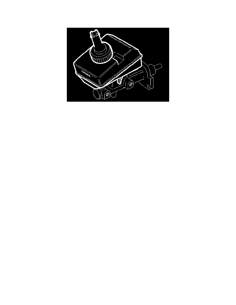
Brake fluid reservoir and level sensor
The brake fluid reservoir is divided into three chambers, two of which are for the brake circuits. One is for the primary and one for the secondary
circuit. This is for safety reasons. If there is a leak in one circuit (e.g. the secondary circuit), there will still be brake fluid in the primary circuit. This
means that the intact circuit will continue to provide full braking power. In manual-transmission vehicles, the third chamber is used for connecting to
the clutch master cylinder. The reservoir has MIN and MAX markings within which the brake fluid level must be kept. The reservoir cap has a brake
fluid level sensor which switches on a warning light on the instrument panel (dashboard) if the brake fluid level is too low. The reservoir is connected
direct to the master cylinder primary and secondary circuit.
The primary and secondary circuit connections to the brake fluid reservoir have safety valves which are normally open. If the brake fluid reservoir
were to come loose from the master cylinder, these safety valves would shut to prevent brake fluid escaping.