
V70R AWD L5-2.3L Turbo VIN 52 B5234T6 (1998)
Hydraulic Modulator Assembly: Description and Operation
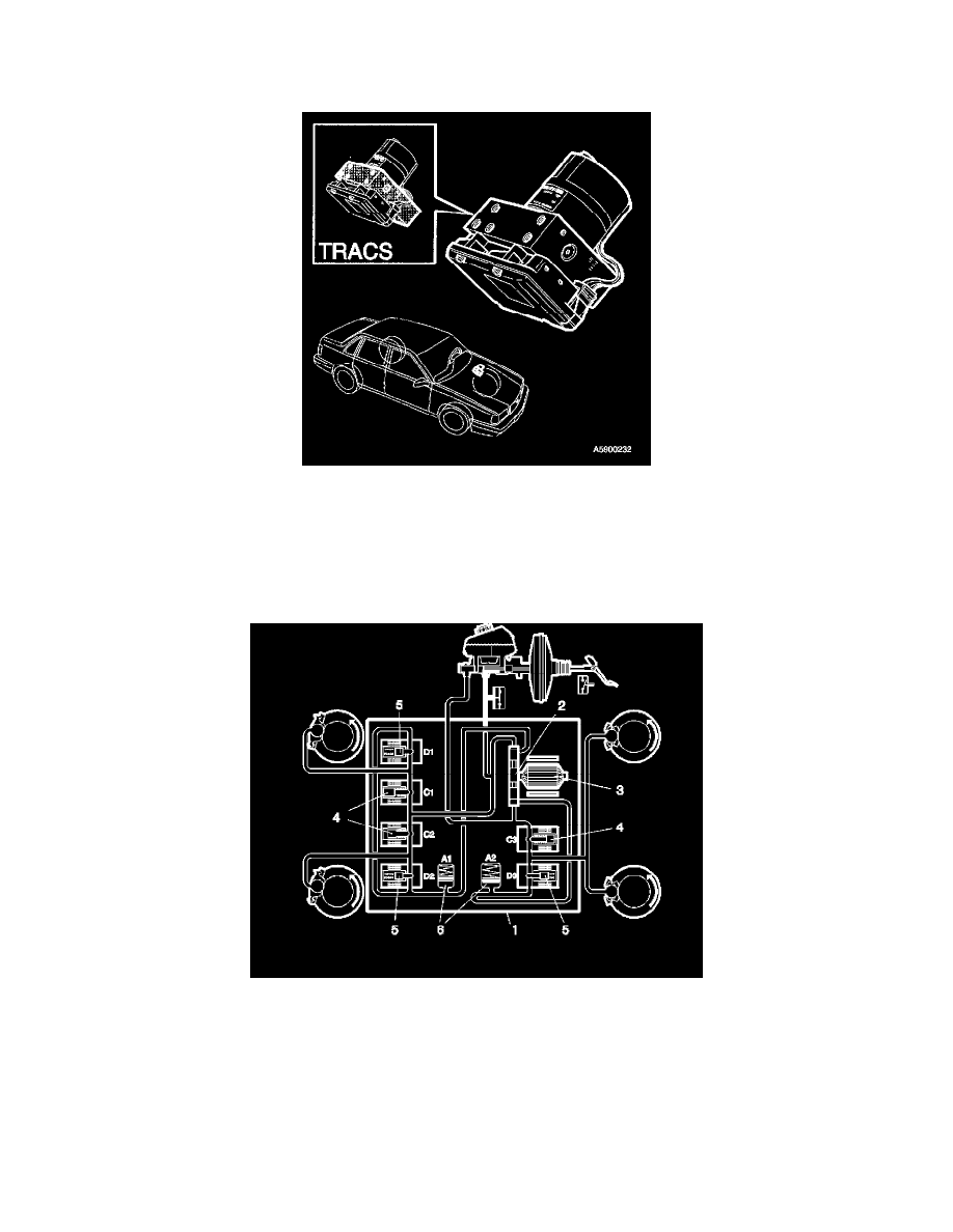
Hydraulic unit
The hydraulic unit (1) is integrated with the control module and is located in the engine compartment. The hydraulic unit consists of a hydraulic pump
(2) of the eccentric piston type and an electric motor (3) in a valve block with inlet valves (4) and outlet valves (5) and a low-pressure accumulator (6).
The electric coils for the inlet and outlet valves are located in the control module.
The hydraulic unit must not be taken apart for repairs, but must always be replaced as a complete unit.
The hydraulic pump, which is operated by a 12 V DC motor, supplies brake fluid to the brake circuits when ABS/TRACS is in use.
The pressure in the brake circuits when using ABS and EBD is governed by the pressure in the master cylinder, and is directly proportional to the
force the driver applies to the brake pedal. The hydraulic unit is oversized so that it can always deliver the necessary flow and pressure.
The control module controls, via the inlet and outlet valves and the hydraulic pump, the pressure to the different brake calipers when braking under
ABS,EBD or TRACS.
The valve block has three internal circuits, one for the LH front wheel, one for the RH front wheel and a common circuit for the rear wheels.
The front wheels are controlled individually, while the rear wheels are under common control, depending on which wheel threatens to lock first.
The valve block has six valves for controlling the brake pressure, three inlet valves and three outlet valves. So, each front wheel has an inlet valve and
an outlet valve, while the rear wheels have a common inlet valve and outlet valve between them. In stand-by mode, the inlet valves are open and the
outlet valves closed. The outlet valves act as non-return valves between the brake calipers and the hydraulic pump.
The valve block has two low-pressure accumulators, one for the primary circuit (1) and one for the secondary circuit (2).
The accumulators are located between the outlet valves and the hydraulic pump and quickly absorb the brake fluid returning from the brake calipers
when using ABS,EBD or TRACS and which the hydraulic pump cannot suck back. This ensures that the brake calipers can release quickly and that
the wheels can speed up quickly.