
V70R AWD L5-2.3L Turbo VIN 52 B5234T6 (1998)
-
detach the brake vacuum hose from the intake.
-
the air duct for the control module box and the Air Cleaner (ACL) air intake hose.
-
the connectors, relays and Canister Purge (CP) valve from the fan shroud.
Place the wiring to one side.
-
the screws for the fan shroud and the relay holder mounting.
Lift up the relay holder and remove the upper hose between the charge air cooler and the intake.
Seal the openings.
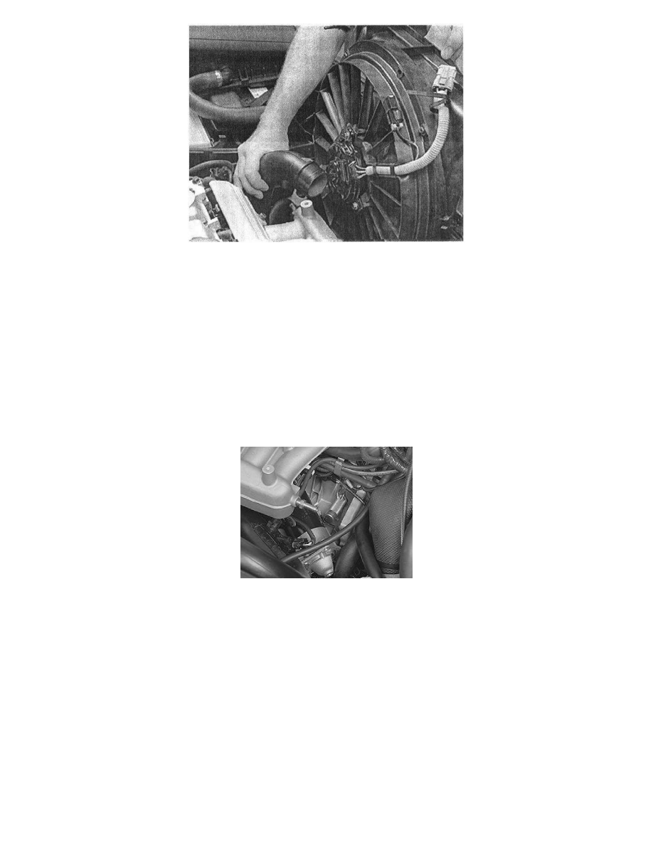
Slacken off the screw clip on the Throttle Body (TB) (electronic throttle module) so that the charge air pipe can be pressed backwards.
Press the charge air pipe backward and lift up the engine Cooling Fan (FC) with its cover.
As illustrated.
Secure the crankshaft position
Install the adjustment tool
Pull the charge air pipe forward
Remove the 3 starter motor screws for the starter motor mounting.
Place the starter motor to one side.
Remove the blind cover plug and the sealing washer.
Turn the crankshaft clockwise slightly to avoid the camshaft adjustment tool being in the wrong position.
Install camshaft adjustment tool: 999 5451.
Ensure that the camshaft adjustment tool reaches down to the cylinder block.
Turn the crankshaft back counter-clockwise until it stops against the drift.
Check that the marking on the crankshaft timing gear pulley corresponds with the marking on the oil pump.
Reinstall
Install the variable Valve Timing (VVT) unit with the toothed belt pulley:
Slacken off, but do not remove, the screws which secure the timing gear pulley to the variable Valve Timing (VVT) unit.
Press the timing gear pulley and variable Valve Timing (VVT) unit on to the camshaft.